I bought a 33R resistor locally, but the BC546 (in my regulator) appears to be obsolete or out of stock everywhere, except on ebay. So I have ordered 5 for £1.75! Let's hope they are legit. I could have had it repaired today if there was a BC546 available.
Rod sent me a new filament regulator, plus the parts to repair the old one. So I did that, and it works fine. I set it all up on the bench, 153V on the anodes, 875mA to the filaments, tried it with a sig gen, a T-amp, and some cheap speakers. Seemed OK, but a bit of hum, so I brought it down and put it into the system. After running an earth lead to the rack, which is not earthed, the hum has gone!
So it works, just need to run it in and fine tune it, a mesh plate AZ1 is worth buying now I know it works, and some valve dampers. I'll clean up the Sowter TVC I bought and try that as the volume control on the output.
This is the first ime I have built an amp from the ground up, all my previous ones were clones, kits or following plans. So a big thank you to several people, Ale for showing what could be done, Rui Lourenco for making such a beautiful version, which I shamelessly copied, at least the layout, Rod for his regulators and help, Andy Evans for advice and parts, but especially to Simon (SJS) for offering to guide me through it and giving me the courage to make the attempt. Without his backup I wouldn't have attempted it.
So what's next? A quality valve phono amp sounds tempting. I just need a design (and help!)😀
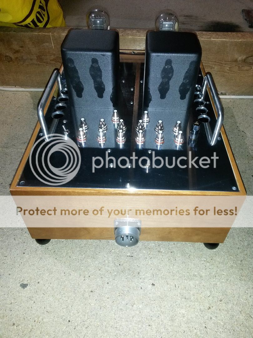
Here are couple of (lousy) pics of it in the system.
So it works, just need to run it in and fine tune it, a mesh plate AZ1 is worth buying now I know it works, and some valve dampers. I'll clean up the Sowter TVC I bought and try that as the volume control on the output.
This is the first ime I have built an amp from the ground up, all my previous ones were clones, kits or following plans. So a big thank you to several people, Ale for showing what could be done, Rui Lourenco for making such a beautiful version, which I shamelessly copied, at least the layout, Rod for his regulators and help, Andy Evans for advice and parts, but especially to Simon (SJS) for offering to guide me through it and giving me the courage to make the attempt. Without his backup I wouldn't have attempted it.
So what's next? A quality valve phono amp sounds tempting. I just need a design (and help!)😀
Here are couple of (lousy) pics of it in the system.
An externally hosted image should be here but it was not working when we last tested it.
An externally hosted image should be here but it was not working when we last tested it.
nice awkwardbydesign but you really need a grid choke LL1670
try it you get all the best the triode can give
and will last longtime
try it you get all the best the triode can give
and will last longtime
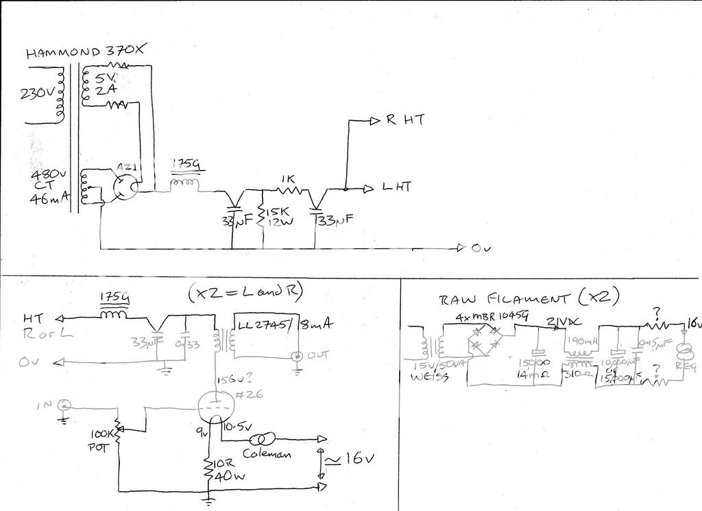
Lundahl LL2745 wired 5.6:1. And the HT PSU is LCRCLC. But the R is 2K4 not 1K.
I recommend to use a second 1K/33uF to decouple the Left / Right Channel from each other - same as you use for both channels, so implement the RC-decoupling for the R-HT at the bleeder resistor.
Thanks. But I'm not sure where I would put the new 33uF cap; they are quite large!I recommend to use a second 1K/33uF to decouple the Left / Right Channel from each other - same as you use for both channels, so implement the RC-decoupling for the R-HT at the bleeder resistor.
At the moment the sound is improving (or my ears are!) as it is running in. Background details and the sense of acoustic space are both becoming clearer, even when the music gets busier. Must try some orchestral or choral pieces.
I recommend to use a second 1K/33uF to decouple the Left / Right Channel from each other - same as you use for both channels, so implement the RC-decoupling for the R-HT at the bleeder resistor.
Joao
The L and R channels are already decoupled from each other, after the 1K / 33uF there is a final LC (175G with 33uF) for each channel, as shown on the circuit diagram.
Are you saying the channel split should be one stage earlier at the bleed resistor? this would require an additional 33uF cap, and changing the 1K to a pair of 2K resistors, and each channel would then be RCLC after the bleed resistor?
The current layout was modelled in PSUD2 and LTSpice and it is stable without LF ringing, so I would be cautious about making changes without detailed investigation.
Cheers
Simon
Or as they say, if it ain't broke don't fix it! It seems to be working OK at the moment, so I will concentrate on small changes (change Welwyn resistors to Mills, mesh plate AZ1, etc), and see if they are improvements.
And I had look at the grid choke idea, but it appears that needs a constant source and input impedance. So using one with a pot on the input, and 5 different sources all with various output impedances is looking for trouble. It seems better suited to a power amp with known impedances. But I will bear all these ideas in mind until I know a bit more. At the moment I'm just elated that it actually works!
I might surround it with scented candles, just for show. 😀
Great build, impressive work. Well done! Go for an 4P1L PSE amp, you won't regret it. Congrats! Ale
Thanks Ale, but I don't think 4-5 watts will work with my 89-90dB speakers! 250W of Parasound Halo A21 does, though. I would like to build a more powerful valve amp one day, (GM70 maybe?) but for now I will stick with the A21. A top class valve phono amp would be more use.
I still can't quite believe it's working so well, with no real teething problems. Following Rui's layout, more or less, certainly helped, although 5 inputs and a replay input from the CD recorder meant I had to put all the sockets behind the output transformers.
 Just need to print some labels for the sockets.
I still can't quite believe it's working so well, with no real teething problems. Following Rui's layout, more or less, certainly helped, although 5 inputs and a replay input from the CD recorder meant I had to put all the sockets behind the output transformers.
I also use 89dB loudspeakers (Acoustic Energy Aelite 3) with A2 capable 300B SET.
In my 4.5m*6m living room it's produce enough energy even listening rock or large symphonic orchestra.
The preamp is CCS loaded #26 fed to S&B TVC.
In my 4.5m*6m living room it's produce enough energy even listening rock or large symphonic orchestra.
The preamp is CCS loaded #26 fed to S&B TVC.
Congratulations "Awkwardbydesign". Your preamp looks great. How does it compare, soundwise, with your previous preamps? I built a 26-preamp some years ago and I still think it's the greatest amplifier I've ever heard.
On a rather different note, I decided to play Creedence Clearwater Revival last night, a nice cheerful album, easy to enjoy. And you know that hifi phrase, "another veil lifted"? Well, this preamp stripped it naked, put on its rubber gloves and did a body cavity search!
The singer was in the bathroom, on his own, but the engineer got bored and decided to switch him left, then right, then back left again. The bass player got lonely, so his friend joined him for few minutes, but got bored and left again. The drummer just did his own thing off in the distance, and so on! I don't know if I'll ever be able to listen to it again, I'm just traumatised! 😱 😀 Oh, and turning the volume down didn't make the band sound further away, they just got very small in the same place.
And I reckon someone who knows these things could probably tell who engineered each track, they are so different. It's terrifying, I may have to put cotton wool in my ears. This was just the rip of the CD, so I will have to play the CD and see if it is different, and then the LP.
Good recordings sound good, but it takes no prisoners, I am hoping it will smooth out as it settles down. But at least my wife is enjoying the extra clarity with her favourite music. 😎
,
Thanks. But I'm not sure where I would put the new 33uF cap; they are quite large!
At the moment the sound is improving (or my ears are!) as it is running in. Background details and the sense of acoustic space are both becoming clearer, even when the music gets busier. Must try some orchestral or choral pieces.
Use instead a 47uF + 47uF capacitor, and it must not be a Black-Gate...
Joao
The L and R channels are already decoupled from each other, after the 1K / 33uF there is a final LC (175G with 33uF) for each channel, as shown on the circuit diagram. Cheers Simon
No they aren't decoupled have a look at the schematic.. there is only ONE 1K / 33uF for decoupling and BOTH channels - L+R HT-rail are connected to the same point.
Are you saying the channel split should be one stage earlier at the bleed resistor? this would require an additional 33uF cap, and changing the 1K to a pair of 2K resistors, and each channel would then be RCLC after the bleed resistor?
You missunderstood me, I recommended to use 2 RC-filters for decoupling the HT-rails after LC-filter; the common point is the C from the LC-filter (and the bleeder resitor) and then connect the 2 33K resistors at that point and use 2 33uF to ground... from there connect each channel to it's own RC-filter.
The current layout was modelled in PSUD2 and LTSpice and it is stable without LF ringing, so I would be cautious about making changes without detailed investigation.
All programs are helpful but they DO NOT tell you how it sounds!!! Instead of wasting too much time with simulation for hours spend time for study the practicing of the old masters.
It's the most transparent I've ever had in my system. I bought a TVC with Sowter transformers to use as the volume control, but as it was a complete working TVC I used it as a standalone pre for a while. It sounded good, but this 26 DHT is a big jump forwards. Anyone who thinks valves sound soft and romantic would get a shock with this pre. I sometimes use Camille's "Music Hole" album for evaluating, as it has some "human beatbox" on it, and hearing the sound of a fist hitting the chest plus the gasp of the voice together is a ruthless test. The acoustic space around Camille's voice is also much bigger; probably artificial but still adds to the overall enjoyment.Congratulations "Awkwardbydesign". Your preamp looks great. How does it compare, soundwise, with your previous preamps? I built a 26-preamp some years ago and I still think it's the greatest amplifier I've ever heard.
After hearing me enthuse about the Rui Lourenco type 26, a friend bought an Audio Music RT1 pre (https://stagaudio.com/amps/audio-music-rt1-pre-amp-5500/), which was a big step forward in HIS system. I am looking forward to taking mine around to his flat to compare.
The rest of my stereo has it's own problems (I need a better DAC, and the tweeters in my speakers will need upgrading, etc), but until the pre has settled down it would be foolish to change too much. Still, onwards and upwards.
No they aren't decoupled have a look at the schematic.. there is only ONE 1K / 33uF for decoupling and BOTH channels - L+R HT-rail are connected to the same point.
You missunderstood me, I recommended to use 2 RC-filters for decoupling the HT-rails after LC-filter; the common point is the C from the LC-filter (and the bleeder resitor) and then connect the 2 33K resistors at that point and use 2 33uF to ground... from there connect each channel to it's own RC-filter.
All programs are helpful but they DO NOT tell you how it sounds!!! Instead of wasting too much time with simulation for hours spend time for study the practicing of the old masters.
Sorry to say this, but you are wrong
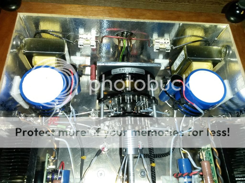
Look at the schematic again, the audio circuit part of the schematic shows (x2 = L + R) and includes an LR decoupling filter before the OTX for each channel
L + R BOTH have an LC filter EACH, they are AFTER the RC filter you are talking about, the channels are decoupled by the LC filters shown on the diagram
the HT is LCRC plus LC per channel
this is confirmed by the internal photos of the audio chassis, which shows two Hammond inductors and two large blue 33uF ClarityCap TC capacitors.
As shown here -
 BTW, Simon, would there be any sonic advantage to replacing the Hammonds with Hashimotos, as in the original circuit?
- Home
- Amplifiers
- Tubes / Valves
- #26 pre amp