")

In my view you have to use filament bias to get the best out of the 26, 10 or 4P1L. No cathode bypass caps - they're out for a start. So do yourself a favour and contact Rod Coleman for a couple of his boards - they're cheap and very, very good. Just about everyone is using them for good reason.
After that you have a choice of anode load. Resistor is cheap as Neskor says, active loads can be good and here go to Ale Moglia's site Bartola Valves and look up his circuits. In both cases you need a coupling cap and I'd use a Russian teflon cap like FT-3, cheap-ish and as good as it gets. I use a transformer because I hate capacitors and eliminate them wherever I can - to my ears they subtly veil the sound. So I'd spring for a Lundahl LL1660/5mA. Cheaper would be a Hammond 126C but I think the Lundahls are worth the extra. Do it once and do it properly.
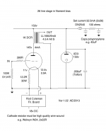
Having said all this I'd use a 4P1L myself, which is what I actually do. It replaced quite a few 26 and 10 preamps and it wasn't a problem with 2v in from my ES9023 DAC. Smaller signals can trigger microphonics, but 2v with a solid 4mm alu chassis and starving the filament a little doesn't bother me at all. With that you need a LL1660/25mA. Anyway here's a 26 schematic.
After that you have a choice of anode load. Resistor is cheap as Neskor says, active loads can be good and here go to Ale Moglia's site Bartola Valves and look up his circuits. In both cases you need a coupling cap and I'd use a Russian teflon cap like FT-3, cheap-ish and as good as it gets. I use a transformer because I hate capacitors and eliminate them wherever I can - to my ears they subtly veil the sound. So I'd spring for a Lundahl LL1660/5mA. Cheaper would be a Hammond 126C but I think the Lundahls are worth the extra. Do it once and do it properly.
Having said all this I'd use a 4P1L myself, which is what I actually do. It replaced quite a few 26 and 10 preamps and it wasn't a problem with 2v in from my ES9023 DAC. Smaller signals can trigger microphonics, but 2v with a solid 4mm alu chassis and starving the filament a little doesn't bother me at all. With that you need a LL1660/25mA. Anyway here's a 26 schematic.
Attachments
Last edited:
Thanks all.
Very much appreciated.
Neskor: I should have been more explicit w.r.t. budget, complication, etc. I can spend a little more to include transformer loading, etc.
I'm happy to give a go at Andy's schematic. One question though, I have an on-hand stock of 26 and 10Y. It seems like some people prefer the 10Y. If you were planning on making this 10Y based, would you modify this 26 schematic (with 0D3 voltage regulator) or use the simple 801A schematic that has been posted by Thomas Mayer? I have some 0D3 on hand as well. I guess it wouldn't take much to make either work (and they are quite similar).
Cheers.
The thing is that if you're going to invest in a LL1660 or something like that, it had better be the right gap for what you want. The 5mA version is good for the 26 or 01A but really not much else. The 25mA version would allow you to use the 4P1L or 10Y. I actually use the 18mA version with the 4P1L just because I happened to have a pair, and that could do nicely for the 10Y as well.
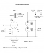
For the 10Y I'm guessing that you might think around 300v B+, -15v and 22mA for instance, though you could experiment. You could use two 150v voltage reg. tubes in that case. The filament supply becomes a lot bigger than with the 4P1L, and Thomas uses chokes which makes it a bit easier to achieve.
I did draw up a schematic but never built it. I'm happy with the 4P1L.
Attachments
#26 and 10/10Y/801/801a also DHT tubes, but quite different animals.
I use #26 (heater bias, CCS loaded, capacitor coupled to TVC) preamp daily, and build and test steadily my 841-10Y-801a PSE amp.
#26 preamp has 220V PSU (250V raw supply+SSHV2 -20ma-), operating point about 170V, 6mA (about 10V on the 10R heater bias resistor), Rod Coleman regulator raw supply is 16V.
#10 preamp needed 350V PSU, SSHV2 (48mA), 28mA CCS, op. point about 250V, 28ma (about 7.5V on the 6R heater bias resistor), Rod Coleman regulator raw supply is 23V.
801a power tubes op. point about 600V, 30mA (-50V).
Thanks for the suggestion euro21. I'll try a range of operating points.
Andy, how important is the value of the bypass cap (0.056 uF) on the VR?
Cheers.
The bypass cap value is very important. Some say it's stable with 1uF but I prefer to stick with 0.56uF, also because it's teflon. You should not under any conditions go over 1uF because it can go unstable. Bigger is NOT better here.
The bypass cap value is very important. Some say it's stable with 1uF but I prefer to stick with 0.56uF, also because it's teflon. You should not under any conditions go over 1uF because it can go unstable. Bigger is NOT better here.
.1 ?
The minimum value is not important and the circuit dont care. Andy might like his one uF and the glowtubes takes it. I would run them at another pace. Everyone fot hens own.
In the usual VR tube circuit there is a dropper resistor in the B+ before the tube. After that dropper resistor the capacitor value is specified as maximum 0.1uF otherwise the tube oscillates. I'm just going by the date sheets here. I replaced the dropper resistor with a DN2540 but as I understand it the capacitor can't be over 0.1uf. It is also possible to leave it out.
Last edited:
.1 ?
Yes, sorry, misprint. It's late here in the UK! That should be maximum 0.1uF.
- Home
- Amplifiers
- Tubes / Valves
- #26 pre amp