Sometimes, using a current meter to measure anode current can cause oscillation. Adding a 10 ohm resistor, and measuring voltage across it, it a better way of measuring anode-current.
Left channel with 10K grid stopper, voltage across 10R 0,143V so 14,3mA
Right channel with 10K grid stopper, voltage across 10R 0,148V so 14,8mA
Last edited:
Felipe,
Your filament current is 900mA.
Without #26 anode/cathode current (B+ turned off), this 0.9A on the 10R (R1) resistor represents 9V.
Is you turn on B+, and measure for example 9.04 V on the 10R resistor, it means that added 0.04V caused by #26 anode current (0.04V/10R= 0.004A.... 4mA).
Your filament current is 900mA.
Without #26 anode/cathode current (B+ turned off), this 0.9A on the 10R (R1) resistor represents 9V.
Is you turn on B+, and measure for example 9.04 V on the 10R resistor, it means that added 0.04V caused by #26 anode current (0.04V/10R= 0.004A.... 4mA).
Attachments
Felipe,
Your filament current is 900mA.
Without #26 anode/cathode current (B+ turned off), this 0.9A on the 10R (R1) resistor represents 9V.
Is you turn on B+, and measure for example 9.04 V on the 10R resistor, it means that added 0.04V caused by #26 anode current (0.04V/10R= 0.004A.... 4mA).
The last measurement the 10R isn't the filament resistor, the 10R is added between the OPT and the anode to measure current.
All electronic tube DIY projects do fall into different levels of skill.
Rod's fillament supply pcb could be considered level 2.
(Because you have to design the power supply yourself).
configuring the filament supply pcb to filament bias will fall into
a higher level 3.
Rods shunt cascode pcb's when available will fall into skill level 5 or 6.
(May be thats why he is taking so long to release them).
When a DIY'er attemptss a project above his level of skill he will naturally face difficulties.
Its normal for such a person to accuse the designer through frustation for misleading him.
Then the designer and others extend help to the novice and educates him to a next higher level to complete his project.
That is the joy of DIY.
Web based DIY survives on that principle.
Accusations and misunderstandings are common in this process and should not be taken
serious by anyone as these will be forgotten soon and appologies will follow.
Person like Rod who is a designer has helped thousands of DIY'ers around the world
with his new ideas, sharing of knoledge and kind advice.
Always remember we the majority of starving DIY'ers look forward to the next post by people like you to widen our knowledge and take us to the next level of skill & joy.
Felipe,
It seems like you are measuring high current due to oscillation, again.
So you will have to try to remove all the possible sources of instability now.
For instance, running long, unshielded grid wires is very risky. These act like a receiving antenna for phase-shifted signals, which are the origin of oscillation. The longer the run of unshielded grid cable, the stronger the pick-up, and the worse it becomes. These will also pick up noise from transformers (etc), and you may get humm. Therefore, this is a bad situation, and you must correct it now, even if it does not fix the immediate problem. Move the input sockets very close to the tube socket, and twist the input and ground wires together tighly (best solution) or use shielded cable.
Nest, use scope on ac 100mV, and 0.1us, 1us, 10us ranges, and check the supply voltage, at the transformer primary. Oscillation?
Rod I desoldered the grid signal wire but still high current, now I will go to check the supply voltage of B+ with the scope.
Felipe, do you have resistor 100K (or lower) to pull the grid to GND?
Grid must not float, at any time, or the anode-current will rise.
Felipe, the grid resistor is very important.
This is one reason I ask for a schematic. It needs to be drawn exactly as you have made the amp, rather than posting Andy's schematic, that you started with. Sometimes, very small differences like the grid resistor, will cause serious problems....
Taking the time to install a proper CAD schematic, like the superb DIPTRACE, or using LTSPICE, will save a lot of time, for everyone.
Rod fixed") was the absence of grid leak resistor, now the current using Andy Sylvanias ST:
was the absence of grid leak resistor, now the current using Andy Sylvanias ST:
Left channel 4,3mA
Right channel 3,3mA
Now I will come back to Cunningham globe to see if really are matched like I bought.
I don't have words to express my deep gratitude for your help.
was the absence of grid leak resistor, now the current using Andy Sylvanias ST:Left channel 4,3mA
Right channel 3,3mA
Now I will come back to Cunningham globe to see if really are matched like I bought.
I don't have words to express my deep gratitude for your help.
Same problem you had last time Merlin
http://www.diyaudio.com/forums/tubes-valves/151421-26-pre-amp-279.html#post3421051
http://www.diyaudio.com/forums/tubes-valves/151421-26-pre-amp-279.html#post3421051
Last edited:
@stajo http://www.diyaudio.com/forums/tubes-valves/151421-26-pre-amp-351.html#post3948270
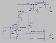
I just changed the Rod Coleman 26 heater regs for the right Rod Coleman 26 filament bias regs, I know 26 amplifies only 6dB or x2, I'm not sure the pre is amplifiying x2 so I attached pics for your advice.
Both regs draws 0,88A, voltage 1.4V.
B+ is 132,1V and the other tube 131.1V, have I to change the OD3?
Attached schematic used. For volume pot I use AVC at the output: is necessary the 100K grid leak resistor?
- Home
- Amplifiers
- Tubes / Valves
- #26 pre amp