Hi!
Those pics and partial diagrams don't really help. Can you post a schematic as it is actually built and connected? Also doing the measurements as suggested would be useful to narrow down the problem.
Also good point from vgeorge. Check your circuit and draw the schematic as is.
Don't forget all ground connections and connections to chassis/safety earth
Best regards
Thomas
Hi!
Those pics and partial diagrams don't really help. Can you post a schematic as it is actually built and connected? Also doing the measurements as suggested would be useful to narrow down the problem.
Also good point from vgeorge. Check your circuit and draw the schematic as is.
Don't forget all ground connections and connections to chassis/safety earth
Best regards
Thomas
Exact schematic
Hi Felipe,
sorry but the latest schematic you posted again did not show how the TVC is wired.
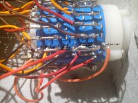
You posted two diagrams of TVC wiring which are different from each other. One of them you got from me. The photo of the switch shows a different wiring than the diagram I sent you.
Best would be if you check all your wiring and draw a diagram which reflects the circuit *as you built it*
Thomas
sorry but the latest schematic you posted again did not show how the TVC is wired.
You posted two diagrams of TVC wiring which are different from each other. One of them you got from me. The photo of the switch shows a different wiring than the diagram I sent you.
Best would be if you check all your wiring and draw a diagram which reflects the circuit *as you built it*
Thomas
Hi!
Sorry but I disagree, since this will not really help to solve the problem. Just recently someone whom I had sent a pair of TVCs emailed me that he was very disappointed about them since they didn't sound as good as the pots he replaced. He also refused to do a systematic analysis, since he trusted his ears more.
It turned out that he had some poor ground connections which caused the problem with the TVC. After fixing this he liked the TVC a lot.
Best regards
Thomas
Try to listen to the AVC by itself, without the active circuit, in order to isolate the problem.
You may even like it more like this")
Sorry but I disagree, since this will not really help to solve the problem. Just recently someone whom I had sent a pair of TVCs emailed me that he was very disappointed about them since they didn't sound as good as the pots he replaced. He also refused to do a systematic analysis, since he trusted his ears more.
It turned out that he had some poor ground connections which caused the problem with the TVC. After fixing this he liked the TVC a lot.
Best regards
Thomas
See my post 3357
http://www.diyaudio.com/forums/tubes-valves/151421-26-pre-amp-336.html#post3697410
TIA Thomas
http://www.diyaudio.com/forums/tubes-valves/151421-26-pre-amp-336.html#post3697410
TIA Thomas
Hi Felipe,
sorry but the latest schematic you posted again did not show how the TVC is wired.
You posted two diagrams of TVC wiring which are different from each other. One of them you got from me. The photo of the switch shows a different wiring than the diagram I sent you.
Best would be if you check all your wiring and draw a diagram which reflects the circuit *as you built it*
Thomas
Now?
Attachments


Your are right Thomas the TVC is wrongly wired, please could you help to wire right? my latest two post with pics are the right wiring?
George connected the TVC without the 26, only sound the left channel distorted and the right channel no sound so the issue are the TVCs.
George connected the TVC without the 26, only sound the left channel distorted and the right channel no sound so the issue are the TVCs.
Hi Felipe,
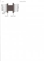
I assume these are the AVCs you got from me? I did send a schematic and detailed description how to wire them.
Note that these have 4dB steps except the first two. So if you wire them as you attempted on your pics, you will get 0,-2,-6,-10,-14dB steps.
If you want 2dB steps you need to wire as per my instructions, that's also why you got a switch with 4 tiers.
Wire the AVCs first and then test the AVC alone (with signal gen and scope) before testing with the preamp
Best regards
Thomas
- Home
- Amplifiers
- Tubes / Valves
- #26 pre amp