Mercury HG3 by Electromekano.
Be very careful.
Be very careful.
Please explain? Because of the Mercury? Or the specific valve-type?
Some thougths on the use of cathode bias..
Intro:
I just (re)built a '26 preamplifier. It is choke-loaded and C-out. PSU is simple but elegant: RGN1064 (X2, used a half wave), 4.7uF, 10He, 60uF, 560R, 120uF and then per channel apart stabilized using a VR-tube.
Cathodes of both '26 share the same filament psu, in series, so one on +1.5Volt and the other on -1.5Volt, centered at ground. The '26's are battery biased on the grid.
My thoughts:
When using cathode bias, imho the use of ONE filament supply would be no problem (not puristic, I know). since the '26 is biased using the voltage drop on a resistor at 1 amp, this nearly is identically to a battery bias since operating the tube at several mA will not affect the cathode bias..
Ergo, using one filament supply for filaments in parallel increases amperage thus allows for lower filament voltage..
Hi Rob,
Nice pre amp !
How is the sound compared to previous version ?
Does secondary winding of transformer for filament have Center tap ?
Errh, yes.. My attempt to share diy-audio experiments and experiences ..
Your web is very helpfull, thanks to share your opinions
")
How is the sound compared to previous version ?
Although hard to be objective on own designs, I would say that sound is very '26-ish, being smooth on the highs profound on the bass but mostly naturally sounding. In this design the coupling capacitors are more or less *the parts* that define the sound character.. I used Sangamo and VitaminQ pio's.. as in the other design it was transformer coupled (2:1).. This one seems to be more dynamically.
Although hard to be objective on own designs, I would say that sound is very '26-ish, being smooth on the highs profound on the bass but mostly naturally sounding. In this design the coupling capacitors are more or less *the parts* that define the sound character.. I used Sangamo and VitaminQ pio's.. as in the other design it was transformer coupled (2:1).. This one seems to be more dynamically.
do you mean the transformer coupled is more dynamic than cap-coupled or other way around?
Diagrams. 1st one is how the preamp is at this time, 2nd one with parafeed (to be) because of reduced gain..
My 71A pre amp is similary to yours very much. I use diode rectifier for negative voltage bias and Regu voltage with Choke in CCS for filament.
How do you think of this schema to get V+, V- for filament ?
Attachments

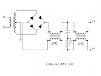
Hi - Please use the circuit shown in the PDF document ANdht01.
The problem here: the rectifier and capacitors must not be grounded at any point - this will cause the cathode-bias to be (near) zero.
The correct circuit is shown in the PDF.
If you like, you can add extra chokes (CMC and differential), but please check that the total dc resistance adds up to about the same as the examples in the PDFs.
You can add extra high frequency caps, to try them out.
do you mean the transformer coupled is more dynamic than cap-coupled or other way around?
Cap-coupled is more dynamic. Imho parafeed config does combine transformer coupled and capacitor coupled configs. I prefer parafeed, that is in my designs so far..
Please explain? Because of the Mercury? Or the specific valve-type?
Mercury tubes in general. Break it under run and its a catastrophy.
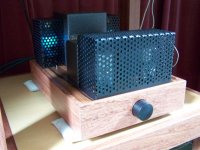
Caged the tubes..
The HG3's because of being mercury-vapor rectifiers.
The '26's to get rid of all remaining hum by stray fields, be it from the amp itself or from other components (even hands when adjusting volume). This allows for all my '26's to be used..
I tried several rectifiers but liked the HG3's the most. They make the amplifier really "fast"..
Preamp is dead silent, at full mu on a sensitive poweramplifier. >Me like<
Attachments
Mercury tubes in general. Break it under run and its a catastrophy.
Ah, okay, thanks.. I am aware of that.. Read a lot about it.
Hi - Please use the circuit shown in the PDF document ANdht01.
The problem here: the rectifier and capacitors must not be grounded at any point - this will cause the cathode-bias to be (near) zero.
The correct circuit is shown in the PDF.
If you like, you can add extra chokes (CMC and differential), but please check that the total dc resistance adds up to about the same as the examples in the PDFs.
You can add extra high frequency caps, to try them out.
Tks Rod,
I like to try your board, but there are some difficulties here...
In my place, I can do for myself this below schema (from Jim de Cort) with point to point connect. Replace LM350 with LT1085. Can I use CMC instead of 2 separate choke ?
I usually connect V-(filament -) to mass via Rk 1-10 ohms, but your schema shows V+ to mass via Rk. It maybe better ?
Attachments
Tks Rod,
I like to try your board, but there are some difficulties here...
In my place, I can do for myself this below schema (from Jim de Cort) with point to point connect. Replace LM350 with LT1085. Can I use CMC instead of 2 separate choke ?
I usually connect V-(filament -) to mass via Rk 1-10 ohms, but your schema shows V+ to mass via Rk. It maybe better ?
Please try with + or - filament connected to ground - and choose the side that sounds best. I usually prefer + side.
The LT1085 regulators are not very low noise, and maybe you will even hear some hiss in the speakers, used in a line amp.
The noise is spread across a wide bandwidth, and will also cause many intermodulation products in the output spectrum - which will degrade the sound.
But it will be quieter than ac-heat, so you can always try.
But without good filament heating, an indirectly-heated triode (or triode-connected pentode) might well be a better choice for making a line amplifier.
Lots of good Russian tubes (IDHT) available very cheaply, and these can give very good sound, even with ac heating.
My 26 Pre Pheaton LC, B+ 170v, was completed today. The sound is very good dynamics. No hummmmm.. 
An externally hosted image should be here but it was not working when we last tested it.
Last edited:
- Home
- Amplifiers
- Tubes / Valves
- #26 pre amp