Is the same problem present on L and R?
This is certainly not expected.
More check points:
- C3 is certainly connected to R8 and R5?
- R5 is 150R?
- R8 is certainly 3.3K?
- Voltage between supply+ and filament + is 2.1 to 2.4V?
- No oscillation on C1.
If no progress, please send me a close-up photo of the Regulator, preferably both sides of the board.
try bypass the L2/c2 just fast test
I tried this, but no change. Thanks!
Abe
Is the same problem present on L and R?
This is certainly not expected.
More check points:
- C3 is certainly connected to R8 and R5? Yes!
- R5 is 150R? Yes(Brn-Gr-Brn-Gold)
- R8 is certainly 3.3K? Yes (Orng-Orng-Red)
- Voltage between supply+ and filament + is 2.1 to 2.4V?No (L channel=3.4, R=3.6)
- No oscillation on C1. Not sure as it is not accessible.
If no progress, please send me a close-up photo of the Regulator, preferably both sides of the board.
I will disconnect the regulator and take pics.
Abe
Do you have a copy of the RCA TT3 Tube Data Book....if not I can email you a copy....page 75 to 77 is worth a read, and it may point you in different direction
Hello,
Thanks. Please email it to me. I sent you a PM for my address.
Abe
Extract RCA TT4
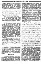
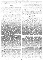
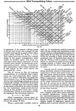
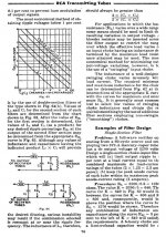
Abe, I can't send you the whole book as its 13 megabytes, However I am sending you here the relevant pages as an extract (5 pages) covering Choke/Capacitor relationships in power supplies. As I said it may point you in a different direction
Abe, I can't send you the whole book as its 13 megabytes, However I am sending you here the relevant pages as an extract (5 pages) covering Choke/Capacitor relationships in power supplies. As I said it may point you in a different direction
Hello,
Thanks. Please email it to me. I sent you a PM for my address.
Abe
Attachments
If I were you this is what I'd do.
1) work on one channel only
2) disconnect the filament regulator and replace it with a simple filtered 12V supply. If you have a computer supply it'll do. Or, power the filament from a 1.5V lab supply and bias the grid with a 9V battery. If it's still oscillating then it's the HV regulator that's got a problem. If it's not oscillating, then it's the filament regulator that needs fixing.
What I'm saying is, leave high quality aspirations aside for a moment, you're in debug mode now. Divide and conquer.
Abe, I can't send you the whole book as its 13 megabytes, However I am sending you here the relevant pages as an extract (5 pages) covering Choke/Capacitor relationships in power supplies. As I said it may point you in a different direction
Hello,
Thanks for this! I tried understanding it but I am afraid I do not have a grasp of what it means.
My circuit is a AZ1 tube(I have 4Vac for filament). From spec sheet, I assume I am operating at about 2x300 V (Va max) and 100mA (Ia max). I am using a Hammond 250-0-250 power transformer.
After the tube, I have 20H then 47uF, then 10H, then 47uF, then 0.36H, then 47uF. Do you think there's something wrong as far as the L and C values according to the excerpts that you sent me?
Thanks,
Abe
Abe,
the book can be downloaded here.... http://www.tubebooks.org/tubedata/TT3.pdf
these are links from Patrick Turner's website... http://turneraudio.com.au/powersupplies.htm and http://turneraudio.com.au/powertranschokes.htm
The ARRL handbooks are also a good source of info about designing choke input psu.... http://www.tubebooks.org/Books/intro_arrl_1941.pdf
http://www.tubebooks.org/Books/arrl_1941.pdf
FWIW, psu designs always starts with the load....
Is the same problem present on L and R?
This is certainly not expected.
More check points:
- C3 is certainly connected to R8 and R5?
- R5 is 150R?
- R8 is certainly 3.3K?
- Voltage between supply+ and filament + is 2.1 to 2.4V?
- No oscillation on C1.
If no progress, please send me a close-up photo of the Regulator, preferably both sides of the board.
Hello Rod,
I sent pics to your email. Just in case, here they are.
Below are pics of two identical reg boards. The one with the heatsink was disconnected from the preamp. Second pic shows the underside. They are identical as far as components(omitting the transistors of course).
An externally hosted image should be here but it was not working when we last tested it.
An externally hosted image should be here but it was not working when we last tested it.
Below is a pic that shows the ground point on the main chassis. here, IEC, 0V, chassis, and cable shields connects to. The IEC from PSU chassis is taken here through the umbilical. The chassis connected to this point as well(which connects to IEC) is taken back to the PSU chassis through the umbilical.
The umbilical(8 pin)wiring is: +1 and -1(filament 1), +4 and -4 (filament 2), +3 and -3(B+, 0V), +2 and -2(chassis and shield, IEC GND). The last pic is the PSU chassis.
An externally hosted image should be here but it was not working when we last tested it.
An externally hosted image should be here but it was not working when we last tested it.
Abe,
the book can be downloaded here.... http://www.tubebooks.org/tubedata/TT3.pdf
these are links from Patrick Turner's website... powersupplies and powertranschokes
The ARRL handbooks are also a good source of info about designing choke input psu.... http://www.tubebooks.org/Books/intro_arrl_1941.pdf
http://www.tubebooks.org/Books/arrl_1941.pdf
FWIW, psu designs always starts with the load....
Thanks Tony!
Abe
26
Abe, please send me the whole circuit diagram so I can look at it. I am sure there is a problem that will only show up on close examination
Abe, please send me the whole circuit diagram so I can look at it. I am sure there is a problem that will only show up on close examination
Hello,
Thanks for this! I tried understanding it but I am afraid I do not have a grasp of what it means.
My circuit is a AZ1 tube(I have 4Vac for filament). From spec sheet, I assume I am operating at about 2x300 V (Va max) and 100mA (Ia max). I am using a Hammond 250-0-250 power transformer.
After the tube, I have 20H then 47uF, then 10H, then 47uF, then 0.36H, then 47uF. Do you think there's something wrong as far as the L and C values according to the excerpts that you sent me?
Thanks,
Abe
Abe, please send me the whole circuit diagram so I can look at it. I am sure there is a problem that will only show up on close examination
Will do! I will draw it out.
Abe
If I were you this is what I'd do.
1) work on one channel only
2) disconnect the filament regulator and replace it with a simple filtered 12V supply. If you have a computer supply it'll do. Or, power the filament from a 1.5V lab supply and bias the grid with a 9V battery. If it's still oscillating then it's the HV regulator that's got a problem. If it's not oscillating, then it's the filament regulator that needs fixing.
What I'm saying is, leave high quality aspirations aside for a moment, you're in debug mode now. Divide and conquer.
Agreed! I just do not have a power supply on hand. I will try to see if I can buy one tomorrow as Ebay takes longer.
thanks!
Abe
Hello Rod,
I sent pics to your email. Just in case, here they are.
Below are pics of two identical reg boards. The one with the heatsink was disconnected from the preamp. Second pic shows the underside. They are identical as far as components(omitting the transistors of course).
An externally hosted image should be here but it was not working when we last tested it.
An externally hosted image should be here but it was not working when we last tested it.
Below is a pic that shows the ground point on the main chassis. here, IEC, 0V, chassis, and cable shields connects to. The IEC from PSU chassis is taken here through the umbilical. The chassis connected to this point as well(which connects to IEC) is taken back to the PSU chassis through the umbilical.
The umbilical(8 pin)wiring is: +1 and -1(filament 1), +4 and -4 (filament 2), +3 and -3(B+, 0V), +2 and -2(chassis and shield, IEC GND). The last pic is the PSU chassis.
An externally hosted image should be here but it was not working when we last tested it.
An externally hosted image should be here but it was not working when we last tested it.
What's with the big blob of solder next to Q2 in the first picture? Is that contacting the body of the cap C1 next to it?
Q1 also looks like it has a solder blob not wetting the pad below it. Try cleaning those up.
.
Last edited:
Hello Guys!
Great news, I figured out what was wrong. It was not the extra filter cap at the filament reg board input using a long umbilical cord. It was the grounding of the individual filament raw DC supply.
Apparently, as stupid as I can be, I had the Negative and Positive raw DC supply outputs cris-crossed between the two floating supply! One positive is using the negative of the other! I found the culprit it at the umbilical cord connector.
Now, I am trying to optimize filament raw DC value as recommended to be around 16.5 to 18.5V.
To Rod, Andy, Iko, James(CV6045), Felipe, Magz, regal, nicoch58, and Tony. Thank you very much for your help and patience! Much much appreciated.
Cheers!
Abe
26
Good!!!! what a learning experience, I bet you know your way that amp with a blindfold on...... enjoy many hours of listening..........
Good!!!! what a learning experience, I bet you know your way that amp with a blindfold on...... enjoy many hours of listening..........
Hello Guys!
Great news, I figured out what was wrong. It was not the extra filter cap at the filament reg board input using a long umbilical cord. It was the grounding of the individual filament raw DC supply.
Apparently, as stupid as I can be, I had the Negative and Positive raw DC supply outputs cris-crossed between the two floating supply! One positive is using the negative of the other! I found the culprit it at the umbilical cord connector.
Now, I am trying to optimize filament raw DC value as recommended to be around 16.5 to 18.5V.
To Rod, Andy, Iko, James(CV6045), Felipe, Magz, regal, nicoch58, and Tony. Thank you very much for your help and patience! Much much appreciated.
Cheers!
Abe
Great
")
Nice troubleshooting!
I'd still clean up those solder joints, though. That's asking for trouble.
I did Magz! Thanks.
Abe
- Home
- Amplifiers
- Tubes / Valves
- #26 pre amp