The 75v glow tubes are pretty spectacular! But for Filipe and for myself as well, I prefer a single tube so you avoid the problems of getting two tubes to strike. Mind, the DN2540 does seem to fire up a couple of tubes pretty well. You can wrap a resistor around the top tube.
I think Mogliaa did some measures and got really good results from some russian VRs combined with a CSS but I dont seem to find it now, the article is probably archived somewhere in his excellent site.
http://www.bartola.co.uk/valves/
Hi Andy,
Attached is a diagram which may explain it better. Since the Filament is fed with AC...hum can be cured by reversing either the Mains input or the leads feeding the filament. If that does not work then trying something like a 0.22uf from one side of the filament to ground also works. I know I have tried this a number of times
We must be talking about different things - there's a few threads going on. Your diagram is OK for the usual kind of AC (or DC) bias with a bypassed cathode resistor, but it's not filament bias, like Abe and Filipe are using. Maybe I missed the post you were referring to.
The 75v glow tubes are pretty spectacular! But for Filipe and for myself as well, I prefer a single tube so you avoid the problems of getting two tubes to strike. Mind, the DN2540 does seem to fire up a couple of tubes pretty well. You can wrap a resistor around the top tube.
I run a CCS-fed VR150 + VR75 on each channel to drop 300V from the supply down to 225V, which is then fed to a second CCS on the plate that drops it down to ~135V or so at 7mA. Sounds excellent.
I don't have any problems with striking them, my trick is to use a choke input B+ supply that depends on the VR tubes to dump enough current to stay in choke input mode. Until they strike the voltage will rise up to that of a cap input supply, ensuring that there is plenty of voltage to strike the tubes. They strike after 1-2 seconds, without fail.
Of course, all the components are rated to easily withstand the max voltage from the "cap input" just in case a VR tube fails.
Attachments
We shall consider the VAC fluctuation as well, thus the reg should operate from 210 to 240 VAC at least.
Waiting for Rod's final word
What about your work in progress?
What about your work in progress?
Still in progress....
 No spare time
Two small pcbs missing. As soon as I will etch the new FolCas RIAA boards....
Still in progress....
Two small pcbs missing. As soon as I will etch the new FolCas RIAA boards....
Please post the pics of the boards in the Simplistic NJFET RIAA thread.
I run a CCS-fed VR150 + VR75 on each channel to drop 300V from the supply down to 225V, which is then fed to a second CCS on the plate that drops it down to ~135V or so at 7mA. Sounds excellent.
I don't have any problems with striking them, my trick is to use a choke input B+ supply that depends on the VR tubes to dump enough current to stay in choke input mode. Until they strike the voltage will rise up to that of a cap input supply, ensuring that there is plenty of voltage to strike the tubes. They strike after 1-2 seconds, without fail.
Of course, all the components are rated to easily withstand the max voltage from the "cap input" just in case a VR tube fails.
\I am surprised that the VR tubes don't add hiss?
\I am surprised that the VR tubes don't add hiss?
Find Ale's measurement and you'll be surprised. Using a good CCS before the VR tube is essential.
Find Ale's measurement and you'll be surprised. Using a good CCS before the VR tube is essential.
And a decoupling usually
Guys, are the VR types having isotopes too? Radioactive valves
From now on I will listen to music wearing lead underwear!
And a decoupling usually
Yeah, I usually have a 100nF MKP across each VR tube. Best to read the datasheet for the correct value.
One nice thing about the VR tubes, they can take quite a bit of abuse. I've had some high value voltage accidentally go across some of mine, and they still work. Too bad I didn't put a film behind me to see how my lungs look. :/
An old airforce radar officer had told me that they had Milspec instructions on how to clean up & quarantine when a voltage regulator tube got broken...From now on I will listen to music wearing lead underwear!
\I am surprised that the VR tubes don't add hiss?
No hiss, in fact dead silence. I have them bypassed with a 0.1uF K40-Y9 oil cap, and the following CCS takes care of any noise that might get past that.
Yeah, I usually have a 100nF MKP across each VR tube.
1 per array if you use them in series is dandy I think.
1 per array if you use them in series is dandy I think.
Yup, I have one 0.1uF across the VR150-VR75 pair.
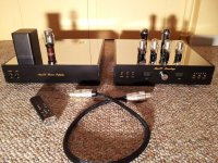
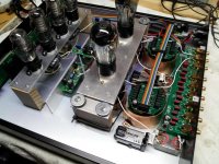
If you look at the picture you can see them in black shrink tubing (so the metal case doesn't accidentally short anything) under the VR tube mounting.
Attachments
Last edited:
I always go through the same routine with filament supplies.
1. On the bench, test the Reg (with heatsinks) connected straight to the two filament pins of a UX4 socket with the 26 in it. I have a bench supply of 30v, 2A (Thurlby Thandar). I gradually increase the voltage up to 5v above the filament voltage - in this case up to 6.5v. I read off the voltage on the filament pins while I'm doing this. I also read out the current on the bench supply, which has a digital readout for volts and current in two separate meters. I wil use a 26 tube that gives me around 1.5v and 1 amp, so I know the tube is in good condition. I then adjust the voltage reg so I get the desired voltage on the filament pins - shall we say 1.5v. I might settle for a starved filament, like 1.4v. I'm now good to go - the filament reg works correctly with an input 5v above the output.
2. I now disconnect one side of the filament wires and place the cathode resistor between the wire from the Reg and the filament pin on the socket. I now have filament bias. I calculate the supply from the Reg that is needed. A 10 ohm resistor at 1 amp gives me 10v bias. Add the 1.5 ohm filaments and we have 11.5v which the Reg needs to supply. So the input to the reg will be 16.5v. I gradually increase the bench supply voltage to 16.5v, measuring the voltage across the filaments of the 26. I'm again aiming for 1.5v. I trim the Reg to get this voltage (or 1.4v etc). This tells me that I'm good to go with a 16.5v supply.
3. I then connect the actual filament supply instead of the Bench supply. The actual supply has to give me something in the range of 16-20v. I will have calculated the size of the transformer needed for this. In my case I use choke input (Hammond 159ZC) so I've factored in the voltage drop for the DC resistance of the choke (0.7 ohms), and I'm assuming the usual calculations for choke input. I connect up the filament supply. I tweak the supply with a small capacitor in front of the choke to get a supply voltage close to what I want - 17-18v will be fine. I'll try caps in the range 100 to 1k ohms, and the voltage will increase with the size of the cap. When I have 17-18v I'm good to go. I then measure the filament voltage and again adjust the Reg so I get 1.5v (or 1.4v etc). I've now finished testing
4. I install the Reg in the preamp chassis. I measure everything again - filament voltage, bias voltage, supply voltage etc. I then leave the supply running for 30m to make sure nothing goes down.
I see numerous posts about problems with implementing filament bias. I strongly urge you to buy and use a good bench supply. A 30v, 2A one is great for this, and it should have two meters - volts and current. You have to constantly measure volts and current when you are building filament supplies for filament bias, and you have to make a number of fine adjustments. Do it all on the bench first and save yourself grief. You must KNOW all the voltages are correct before you install your filament bias supply in your chassis. Follow the correct procedure step by step, be careful at all stages, and measure, measure, measure.
If you use Rod Coleman regs which I and many others recommend, make sure Rod gives you the right resistor values for the filament bias you intend to use. Tell him when you order. The resistor values differ according to the supply voltage you need to provide. He is well aware of all this and gives detailed instructions with his kits. Rod is an uber-professional guy!
I attach a picture of the bench supply type I use. You can use something similar with dual readouts for volts/current. Should be plenty on ebay, new and used. Like I say, 30v at 2A is good for filament bias. I use filament bias for ALL my stages - even the outputs which are parallel 4P1L in PSE. The supply voltage for those is 28v at 1.3A with a 15 ohm cathode resistor. In actual fact, I have a few Thurlby bench supplies and as we speak my PSE 4P1L outputs are running off two 30v 2A supplies into Rod's regs. If you have a couple of bench supplies you can be lazy and use those. They sound great.
Hello guys!
Thank you Andy for your valuable time and tips! As always, It is so easy to understand how you explain things to me.
Anyways, I now have 1.48Vdc at filament for both tubes(measured between pin 4 and 1) and 9.67 Vdc and 9.9 Vdc on each 10R cathode resistor. Also, I have from CCS/Shunt Regulator measured 150Vdc regulated after CCS at 30mA resulting to 145 Vdc for each plate of the tubes. I kept this figures for about an hour and re-adjust a tiny bit on the filament voltage to where each are sitting now at around 1.48 Vdc. I am good to go!
Just waiting for my input selector rotary switch and I will take a listen probably tonight or tomorrow. I will get myself a decent power supply for setting the filament bias boards.
Abe
Last edited:
- Home
- Amplifiers
- Tubes / Valves
- #26 pre amp