I haven't grounded the cathode resistors, Rod told me his filaments regs must be connected floating never connected to ground.
Normally in a PSU you ground after rectifiers. But in in the PSU for Rods filament thingie you cant do that, because you will have a ground loop if the filaments are also grounded. I guess that is what he ment by that.
So you dont ground PSU for Rod-thingie, just the filaments.
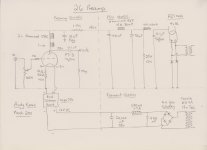
So let' s say you have one transformer 0-250. Where do you connect the ground on your PSU? In your simulation you showed that you have a 229-0-229 transformer.
I' m puzzled.
Also as Erik said, you should ground the point where the 10R resistor and - of Rod' s supply meet.
I' m puzzled.
Also as Erik said, you should ground the point where the 10R resistor and - of Rod' s supply meet.
OK. First get the filament supply right, then look at the PSU. Don't connect up the B+ until the filament supply is working correctly. You should now have about 11v on the top of the cathode resistor, and the bottom is connected to ground. What is the actual voltage you have now on top of the cathode resistor?
That's because psud don't have hybrid graetz rectification.
Both 10R grounded
Bingo, my last psu cap isn't grounded, thanks George.
That' s why no current was flowing!
Do the tests Andy says before applying B+ again.
Current wasnt flowing because the cathodes had no relation to ground, which in this case is minus in the circuit. The circuit was open and could not pass current. If last filtercap was not grounded, it just stopped filtering, but it has nothing with current flow to do since a capacitor can not pass current.
Last edited:
OK. First get the filament supply right, then look at the PSU. Don't connect up the B+ until the filament supply is working correctly. You should now have about 11v on the top of the cathode resistor, and the bottom is connected to ground. What is the actual voltage you have now on top of the cathode resistor?
I have 9,33V left channel & 9,75V right channel, my cathode resistor is 10 ohms.
Last edited:
With filament bias it is important to connect everything in the right order. This is -
1. Connect Rod regulator up. Minus to ground, plus to pin 4 of 26
2. Connect resistor from pin 1 of 26 to ground.
3. Insert tube and turn on regulator
4. Measure across pins 1 and 4 for 1.5v
5. Measure from pin 1 to ground - for 10 ohm resistor should be about 10v, since current is 1 amp. Use ohms law.
6. Leave the supply on for about 30m to make sure it is stable.
AFTER you have done all this and the voltages measure the same after 30m, you can connect the B+.
I have 9,33V left channel & 9,75V right channel, my cathode resistor is 10 ohms.
That's pretty good - you have about 950mA current, so your voltage across the filament should be about 1.4v. Slightly starved - very good.
Now you can connect the B+
What I would say, though, is don't work late because you can make mistakes. I always test circuits in the daytime, never late in the evening.
Andy
Last edited:
With filament bias it is important to connect everything in the right order. This is -
1. Connect Rod regulator up. Minus to ground, plus to pin 4 of 26 CONNECTED TO PIN 1, DONE
2. Connect resistor from pin 1 of 26 to ground. CONNECTED TO PIN 4, DONE
3. Insert tube and turn on regulator DONE
4. Measure across pins 1 and 4 for 1.5v DONE
5. Measure from pin 1 to ground - for 10 ohm resistor should be about 10v, since current is 1 amp. Use ohms law. FROM PIN 4 TO GROUND 10V DVM PLUS LEAD TO PIN 4 DVM MINUS LEAD TO GROUND
6. Leave the supply on for about 30m to make sure it is stable. OK
AFTER you have done all this and the voltages measure the same after 30m, you can connect the B+.
- Home
- Amplifiers
- Tubes / Valves
- #26 pre amp