When you are modelling the high value capacitors in a power supply, please double-check the ESR given in the data for the caps.
For example, the Panasonic TSUP series of parts is recommended, where the ESR is 38mOhm for 22000uF.
http://panasonic.com/industrial/includes/pdf/PIC_aec_ts-up.pdf
adding the correct ESR to the model will make a big difference to the accuracy of the ripple model.
For example, the Panasonic TSUP series of parts is recommended, where the ESR is 38mOhm for 22000uF.
http://panasonic.com/industrial/includes/pdf/PIC_aec_ts-up.pdf
adding the correct ESR to the model will make a big difference to the accuracy of the ripple model.
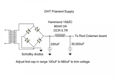
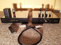
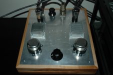
Here's the type of filament supply I use. I strongly recommend filament bias rather than battery grid bias. I've tried both. With filament bias you eliminate the capacitor on the input. I consider it important to eliminate all capacitors that could influence the signal path, and to use polypropylene caps in the PSU.
Attachments
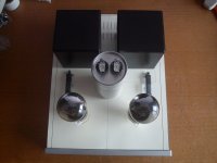
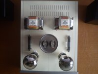
Do you like the chassis distribution for #26? The heatsink inside the chassis without pcbis for Salas SSHV2 shunt regulator. The empty centered space inside the chassis is for the TVCs.
Attachments
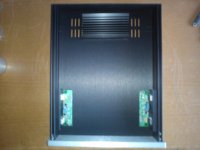
That's a nice looking chassis! Where did you get it?
Thanks, it's a Galaxy Maggiorato form modushop - hifi2000, the exact model is code 1NGXA288 230mm x 280mm
1x frontal in aluminum 10mm oxidized silver
1x back in aluminum 3mm oxidized black;
2x flanks in aluminum of 10 mm oxidized black ,
2x covers in alu 2mm oxydized black
Dimensions:
Width: body 230mm, inner useful 210mm
Height: 80mm
Depth: 280mm
Weight: 2,0 KG
Web link: modushop.biz
Merlin,
I have been designing something similiar (SSHV's + coleman regs) for a headamp.
How are you going to handle the power supplies? I understand the Coleman doesn't like the dc supply to the filaments to be run on the same umbilical as the pre filtered B+. My experience is that its best to keep all power transformers as far as possible from the OPT's. I've literally measured -25db per foot 60hz reduction separatig output transformers from power transformers. Three chassis just seems crazy to me.
I have often wondered if for an amp like this if it would be best to just make the power supply chassis AC only, and do the rectification for both the regs and B+ in the amp chassis. It always makes sens to "transmit" ac rather than DC, but I don't know how much buzz the 26's would pick up from rectifiers in close proximity.
Last edited:
Merlin,
I have been designing something similiar (SSHV's + coleman regs) for a headamp.
How are you going to handle the power supplies? I understand the Coleman doesn't like the dc supply to the filaments to be run on the same umbilical as the pre filtered B+. My experience is that its best to keep all power transformers as far as possible from the OPT's. I've literally measured -25db per foot 60hz reduction separatig output transformers from power transformers. Three chassis just seems crazy to me.
I have often wondered if for an amp like this if it would be best to just make the power supply chassis AC only, and do the rectification for both the regs and B+ in the amp chassis. It always makes sens to "transmit" ac rather than DC, but I don't know how much buzz the 26's would pick up from rectifiers in close proximity.
I believe that the wiring between the Trasformer->Rectifier->Cap is actually the routing priority, for any dc supply - HT or filament. This is due to the high pulse-currents in the rectifier every time the caps are recharged at the top of the mains waveform. These repetitive peak current are often very high compared to the dc current (depends on C value). I prefer to have these wires as short as can be - to avoid coupling of the current pulses into the signal wiring. The shorter the rectifier wires, the less likely this can happen.
If you want to run all the supplies in one umbilical from power chassis to signal chassis, it will still work OK. For preference, shielded cable for the filament supply, and put 1000-2200uF Panasonic FC at the input of the Filament regulator. Still, 2 separate umbilicals is my choice, in a no-compromise system.
There are some nice modular chassis from Lincoln Binns as well. They have side extrusions and come in 66mm, 88mm (2U) and 132mm (3U) heights.
Custom Extruded Case UnioBox 2 | Lincoln Binns
All kinds of widths and lengths are available. Prices are similar.
http://www.lincolnbinns.com/wp-cont...ns-Ltd-UnioBox2-Price-List-September-2011.pdf
Custom Extruded Case UnioBox 2 | Lincoln Binns
All kinds of widths and lengths are available. Prices are similar.
http://www.lincolnbinns.com/wp-cont...ns-Ltd-UnioBox2-Price-List-September-2011.pdf
Attachments
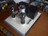
I have the B+, L/R filaments and remote control power all in the same umbilical, with each pair twisted and shielded. Coleman supplies have 1000uF cap at input, B+ is regulated with VR tubes in the preamp chassis, 26s have cascoded CCS plate loads. My filament supply has ~10mV of ripple when it exits the PS chassis. The pre is dead quiet.
Attachments
I have other identical box for PSU but I'm not sure if the box can fit all txs for B+, choke, #26 filaments and AZ1 filaments: in total 5 transformers. Also the psu for Rod Coleman are big, I don't know if finally will be 2 or 3 chassis or buy other big chassis for psu and left the 2nd identaical chassis for 4P1L.
Any advice for other best distribution of #26?
Any advice for other best distribution of #26?
Last edited:
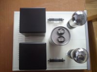
I have two boxed layout.
Preamp box contains tubes, cascode CCSs, -old style DIY- R. C. regulators, 10R/50W Dale resistors -with large PC heatsinks-, input selector and TVCs.
I impact to the ugly and heavy power box HV raw supply -CLCLC-, two SSHV2, and two LV raw supplies -each C-CMC-C-L-C type-.
Between two boxes one umbilical contains twisted, but unshielded cables.
Attachments
Rod what about to using the side chassis as heatsink for your heater regs.? If OK will be a way to safe space inside the #26 chassis.
Hi Felipe,
Yes - using the chassis for Filament Regulator heatsinks will be perfect. This is a good method to allow the heat to reach the outside air.
Here's the type of filament supply I use. I strongly recommend filament bias rather than battery grid bias. I've tried both. With filament bias you eliminate the capacitor on the input. I consider it important to eliminate all capacitors that could influence the signal path, and to use polypropylene caps in the PSU.
Hello Andy,
Below is the 18V raw DC supply I modeled with the schematic you posted.
An externally hosted image should be here but it was not working when we last tested it.
One more question, for the AZ1 filament, can I just use 5VCT tap(eg. power transformer) and calculate the dropping resistor to drop 1V at the rectifier current draw? What do you use for your AZ1 filament?
Thanks!
Abe
- Home
- Amplifiers
- Tubes / Valves
- #26 pre amp