Ok,
I have searched the forum and found very little definitive info on this subject.
Here is my quandry
I am designing a PP output stage using 2 x 829B's. They will be Triode strapped and paralleled. (don't ask why these tubes..I just like a challenge)
I am having a tough time calculating the Miller Cap of these tubes. It gets complicated because a: the two sections are parallel and B: its a pentode "triode strapped"
Inter-element caps are as follows per section
Cgk 14.5
Cak 7
Cga 0.12
Stage gain will be about 8-9 maybe.
I realize that some of these values will double due to the parallel connection but can someone help me with the method of calculating it?
I need to know how low I need to get the output impedance of the driver stage to keep response up to 25Khz or so.
Thanks for the replies but I still don't have a definitive answer.
What is the formula for this type of calc?
In theory it is:
Cin = Cgk + [(Cg1a+ Cg1g2) * gain]
The problem is in finding a datasheet which gives you a genuine value for Cg1a. Cg1g2 may also be hard to find, but is probably less important.
In theory it is:
Cin = Cgk + [(Cg1a+ Cg1g2) * gain]
The problem is in finding a datasheet which gives you a genuine value for Cg1a. Cg1g2 may also be hard to find, but is probably less important.
Cg1-a is very small in pentodes, and Cg1-g2 is typically 20-30% more than the Cg-a of a comparable triode. With a pentode, g2 becomes part of the anode and is multiplied in the Miller effect.
cheers,
Douglas
Thanks for the replies but I still don't have a definitive answer.
What is the formula for this type of calc?
I estimated Cag1 and multiplied it on stage's voltage gain.
Well the data I have been able to find is as follows
Cgk = 14.5 (also listed as input C) so I am assuming Grid 1 to cathode
Cak = 7 (internal capacitance of plate to cathode)
Cga = 0.12 grid to plate
I found spec that shows the capacitance of G2 to Cathode including the capacitor is approximately 65pf
G3 is tied to the cathode.
So, with these numbers what do I do?
G2 tied to the plate and is part of the load so where does the 65pf fit in? Ignored correct?
Cak also load it is ignored also?
Do I ignore the G1 to G2 capacitance or make one up?
so if I take the Cga and double it (for parallel) and multiply by 10 (gain 9 +1)
I get 24pf
Then add twice the Cgk = 29pf I get 53pf??
The "elusive" Miller Capacitance of TS Pentodes/Beam Power Tubes
Everyone Thank you very much for the replies.
It seems to me that this is an "elusive" calculation.
Can anyone explain to me what capacitances are part of this and which ones can be ignored?
I have been playing with tubes for a while now. I have literally read through numerous tube manuals and papers. I am on the verge of a "breakthrough" where I will actually be DESIGNING amplifiers with specific goals in mind rather than just moving operating points on established designs.
Estimates are good but a more accurate calculation makes me feel better.
Because of my limited budget certain things are out of my reach. So an interstage tranny in this amp is out of the question. I would also like to keep the tube count down so I am trying to see if cathode followers will be needed in the driver stage.
Can anyone point me to a good resource on miller capacitance?
Last edited:
Cg1-g2 is typically 20-30% more than the Cg-a of a comparable triode.
I don't understand clearly the above.
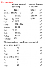
It's more easy if the manufacture shows the specs like this D3a tube. And then we can calculate C-Miller and estimate its effect.
Does anyone can tell me what relation between Cinput, Coutput, Cgk, Cga, Cg2g1.... ?
C-Miller is different to Cinput ?
Attachments
Last edited:
Cmiller is the input capacitance due to the Miller effect multiplying the in-out capacitance. Cinput includes Cmiller, but also Cgk, Cgh and maybe others C's too.
Cg1-g2 may be more than Cg1-a because g2 is nearer the cathode than the anode. However, g2 is a grid not a solid plate so that reduces C. On the other hand the way electrostatics works means that g2 acts almost like a solid plate (the electric field almost fills in the gaps) so C can be bigger than you expect.
Calculating Miller capacitance is easy. Find the numbers to put into the calculation can be difficult.
Cmiller is the input capacitance due to the Miller effect multiplying the in-out capacitance. Cinput includes Cmiller, but also Cgk, Cgh and maybe others C's too.
You means:
Cinput = C-Miller + Cgk + ...
Is it right ?
In case of calculating C-Miller for a penthode tube in triode mode, we can use Cinput (in triode mode) to know how is Miller effect.
If we have no data of Cinput at triode mode, or also no data of Cg1-g2, then How do we calculate C-Miller ?
Last edited:
One option might be to measure input C by changing the source resistance and looking for the change in HF rolloff.
I usually use an oscilloscope, a (properly adjusted) 1:10 probe and a resistor. Connect the scopes calibration square wave through the resistor to the 1:10 probe and measure how long it takes after a step to reach 1-1/e~=0.63212 times the final value. Then connect the unknown capacitor in parallel with the probe and measure again. The difference between the time constants divided by the resistance is the unknown capacitance. The resistor must be large compared to the impedance of the square wave source.
A problem with this method is that it gets inaccurate when the capacitance to be measured is small compared to the probe capacitance, as is probably the case with Cg1-g2 of a valve.
- Status
- This old topic is closed. If you want to reopen this topic, contact a moderator using the "Report Post" button.
- Home
- Amplifiers
- Tubes / Valves
- Miller Capacitance of triode strapped pentode