"CCS in the tail. Doesn't this prevent M1 thermal runaway already? "
Certainly would with the two CCS's in the tail scheme. ( cap coupling)
Sure.
Why not balance the toroid's current with only a pair of cheap MPSA42/92 transistors? You're only working at 250V.
And while you're there, throw out the battery and depletion FET and use a cheap enhancement power FET - easier circuit, and make it adjust the balance automatically.
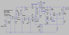
Aim to run the pentode at the standard 36mA. When it's warmed up, R11 (33R) senses toroid current and you get 1.2V. This puts about 0.6V across R17 (620R) and programmes 1mA in Q1. R16 thus reflects the same voltage as R17.
When the currents are balanced, R18 will drop the same voltage as R11, turning ON Q1, and stabilising the power-FET current. If the currents are not balanced, Q4 will servo the MOSFETs gate until it's right. C1 & R20 set the low-frequency action of the servo.
When you power ON with a cold valve, the FET side will stabilise with only ~18mA flowing. As the pentode cuts in, the rising voltage on R16 causes the FET current to ramp up with the valve, giving you a soft-start.
If you use decent 1% resistors it should balance to within 2 or 3mA, and you can make R16 = 470R + 200R trimmer if you want it exact. The tempco of the two Vbe are self-cancelling, so temperature stability should be good, too.
The tail's current source could be built with a pair of cross-coupled MPSA42s as well, if you like a nice low build cost. (MPSA42 are less than 10p/15cent)
Keep the wiring short with transistor current sources, or you will need to use ferrite beads/chips to prevent oscillation.
And while you're there, throw out the battery and depletion FET and use a cheap enhancement power FET - easier circuit, and make it adjust the balance automatically.
Aim to run the pentode at the standard 36mA. When it's warmed up, R11 (33R) senses toroid current and you get 1.2V. This puts about 0.6V across R17 (620R) and programmes 1mA in Q1. R16 thus reflects the same voltage as R17.
When the currents are balanced, R18 will drop the same voltage as R11, turning ON Q1, and stabilising the power-FET current. If the currents are not balanced, Q4 will servo the MOSFETs gate until it's right. C1 & R20 set the low-frequency action of the servo.
When you power ON with a cold valve, the FET side will stabilise with only ~18mA flowing. As the pentode cuts in, the rising voltage on R16 causes the FET current to ramp up with the valve, giving you a soft-start.
If you use decent 1% resistors it should balance to within 2 or 3mA, and you can make R16 = 470R + 200R trimmer if you want it exact. The tempco of the two Vbe are self-cancelling, so temperature stability should be good, too.
The tail's current source could be built with a pair of cross-coupled MPSA42s as well, if you like a nice low build cost. (MPSA42 are less than 10p/15cent)
Keep the wiring short with transistor current sources, or you will need to use ferrite beads/chips to prevent oscillation.
Attachments
Will try this one. It should be troublefree enough with a separate CCS on the MOSFET to prevent thermal runawayas discussed.
Just bought a small CPU-cooler with fan, 5*5*5 cm. Should be enough for both channels without running the fan at full speed. Three leads to the fan though, anyone who knows how it is connected?
Just bought a small CPU-cooler with fan, 5*5*5 cm. Should be enough for both channels without running the fan at full speed. Three leads to the fan though, anyone who knows how it is connected?
An externally hosted image should be here but it was not working when we last tested it.
Beware the sample-to-sample variations in depletion-FETs - they can give quite widely different current for the same resistor. And they are expensive, aren't they (more than a P/ECL86, for sure).
You still get unbalance from variation in screen current, too.
Have look at the self-balancing PP in the circuit above, less errors, no nasty 1000uF, much less cost!
You still get unbalance from variation in screen current, too.
Have look at the self-balancing PP in the circuit above, less errors, no nasty 1000uF, much less cost!
Beware the sample-to-sample variations in depletion-FETs - they can give quite widely different current for the same resistor. And they are expensive, aren't they (more than a P/ECL86, for sure).
You still get unbalance from variation in screen current, too.
Hey Rod,
So you didn´t think R14 and R31 should be adjustable
") ?
? About cost I think an IXYS 1000V costs 0,7EUR at Mouser.
About variations if screen-current we have a 6B4G-6L6 selfsplit up and running since about a year ago. Plays great. In that one we use a bjt current-mirror between the cathodes. It is in a thread somewhere here at Diyaudio.
Lars, sure you can make the resistors adjustable - but better still if the circuit balances without adjusters.
6L6 is same structure as the 807, which Shoog reminds us, has unusually low screen current. Again this is OK, but it is even better yet, if the screen current does not cause any current unbalance in the trafo.
6L6 is same structure as the 807, which Shoog reminds us, has unusually low screen current. Again this is OK, but it is even better yet, if the screen current does not cause any current unbalance in the trafo.
Hey Rod,
You are absolutely on the right track about sensing above the tube. But why add R11 when the OPT has resistance?
Couldn´t you just take the reference voltage at ECL86s anode?
A possible drawback could be that R18 is in series with the lowZin input/source of M1.
Would be a good thing if all sensing could be held "above".
I guess the time-constant from R20, C1 blocks AC?
Lars,
If you sense at the anode you will expose the transistor [base] to + and - 200V or more, and some damage is tough to prevent. The low value of the current-sense resistor keeps the voltage swing to a few volts at most.
The MOSFET has a low input impedance only when the drain current is high. For instance for the IRF740 you get a gm of 4S at 5A - but at 36mA the value will scale down and be quite small. The Source equivalent resitance is 1/gm and will be comparable to the 33R sense resistor. The actual value you choose is a compromise between accuracy (high value best) and low impedance. OK, you choose!
Actually, sensing both sides "from above" is possible: just add another PNP and 33R in the drain circuit, and 1240 Ohms in the Q4 base - then you can eliminate the 33 Ohm in the source circuit completely!
In my implementation, where I have used back to back 1000uf caps to link the cathodes (with suitable film bypassing), I have noticed almost no sonic impact. I can say this because I have ran such a configuration up against a Nelson Pass F5 and my amp came a very very close second (a matter of taste really). I have also built a headphone amp with the same output stage and it beat all competition. Since I think you would generally agree that the F5 is one of the cream of SS amps, having been the cumulation of decades of developement, you will see that the large back to back bypasses are almost unnoticable in reality.
There is a white paper somewhere describing why back to back electro's can perform so well. I also observed that Thorsten recommended this configuration as an input/output blocking cap arrangement over all other cap options.
Hope that helps.
Shoog
There is a white paper somewhere describing why back to back electro's can perform so well. I also observed that Thorsten recommended this configuration as an input/output blocking cap arrangement over all other cap options.
Hope that helps.
Shoog
Hey Rod,
Thanks for leading a blind through the sand-jungle!
What happens to gm at the lowish 36mA with the IRF740 you mention?
Care to modify your schematic as I don´t follow completely?
Thanks for leading a blind through the sand-jungle
!The MOSFET has a low input impedance only when the drain current is high. For instance for the IRF740 you get a gm of 4S at 5A - but at 36mA the value will scale down and be quite small.
What happens to gm at the lowish 36mA with the IRF740 you mention?
Actually, sensing both sides "from above" is possible: just add another PNP and 33R in the drain circuit, and 1240 Ohms in the Q4 base - then you can eliminate the 33 Ohm in the source circuit completely!
Care to modify your schematic as I don´t follow completely?
The gm of a power FET is not characterised at low currents, but just like a valve, it gets smaller as current goes down. A big channel gives more gm to begin with, so selecting a high-current FET may help if you need more gm.
This is one reason that a bipolar transistor is a much better follower than a FET (or a valve): the gm of a BJT is about 40 x Ic (mA).
Schematic? OK! how about this!
This is one reason that a bipolar transistor is a much better follower than a FET (or a valve): the gm of a BJT is about 40 x Ic (mA).
Schematic? OK! how about this!
Attachments
Last edited:
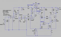
In Rod's last schematic, post #32, I would just combine R17 and R22 as the same resistor. Now it's a diffl stage, which already takes the difference of sampled primary currents, so Q4 and R13 can be eliminated. Connect R20 to the R14, R16 junction. Change R18 to 240K to match R14. Some adjustment of R16 resistance likely to get correct M1 bias. (half of R17/R22 current thru R16 gives bias voltage)
A small further improvement would be to change the merged R17/R22 to a CCS, then the currents from R16 and R18 into the common cathode/source at bottom will be constant. (they should be near constant anyway without the CCS, but we are concerned here about minute distortia currents for SE effects)
Then to fix the screen current issue, using Ken's preferred technique, connect a Zener diode between the cathode and screen of U1 (zener voltage = to screen - cathode voltage). Adjust value of R15 to supply max screen current. This way screen current will be subtracted (approximately; exactly if R15 is a CCS) from the cathode current. The bottom CCS, M3, must supply U1 plate current + R15 current + M1 current.
notes:
The gm of Fets is approximately proportional to drain current, so one can do a rough estimation of gm by scaling down the datasheet gm at rated current. Can always measure one with a power supply and meter too.
Shoog's dual CCS and dual caps approach may be fine as he says. I would still consider putting in the screen current fix there though, or at least try it anyway. It's possible that uncorrected screen current may come close to compensating the non-linear increase of plate current at large signal if the screen resistor is adjusted optimally.
Don
Last edited:
 looking good!
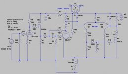
 Hmmm, oops, I think we may need to include low pass filters (just DC level wanted) on the sampled current signals (R11,R21) going into Q1 and Q2, since the AC signals are not coincident in time.
I just wish that the conventional tube OTs had separate primary windings too. So much more flexible.
Last edited:
Rod and Don,
Did some sims in my lunch-hour on the latest version. Think R22 must be of higher value to get better tracking at a wider area.
Also tried the DN2540 by returning the resistors (with changed values) to ground instead of the cathodes. In the simmed world it didn´t look much worse.
Did some sims in my lunch-hour on the latest version. Think R22 must be of higher value to get better tracking at a wider area.
Also tried the DN2540 by returning the resistors (with changed values) to ground instead of the cathodes. In the simmed world it didn´t look much worse.
"to get better tracking at a wider area. "
If you haven't already, put RC low pass filters between R11, R21 sensors and the Q1, Q2 diffl. pair. (series R and big C across diode to B+ for each side, maybe like 10K Ohm and 100 uF). Any AC signal in the system would eat up the headroom on the diffl. pair, so the filters keep that out. The DC diff. error signal is quite small in comparison.
Hmmm, not sure about the diodes D1, D2 Rod put in there. Maybe they are intended to limit the active range to near zero crossing of the AC signal? Could try without the diodes with the low pass filters installed.
I guess the diodes are just for protection of Q1 and Q2, being reverse oriented, so they won't affect operation.
Could just use one cap for the RC filters by connecting it from one side to the other, ie Q1 base to Q2 base since this is running in class A.
Last edited:
- Status
- This old topic is closed. If you want to reopen this topic, contact a moderator using the "Report Post" button.
- Home
- Amplifiers
- Tubes / Valves
- Spud, Schade, PP, Anti-triode ECL86