Proceed with those builds, they will help you make tidy and clean wiring. Then you will be able to determine if there are issues or not.pardon me,the pictures did not upload the first time, so here it is.
Hey! You wonder why you have hum! The pics say the whole story.
Don't even bother to fix it in this style. Seriously.
+++++++++++++++++++++++++++++++++++++++++++++++++++++++
Hi Salas, i dont quite understand the deviation here. maybe you can share with me on things which are deemed wrong here. the parts on the board have been moving around with no effect on hum. the TXs are now in the wrong position but have been also in the 90deg off position with no effect. maybe they are far apart for induction (1ft away).
the caps are shown here below, so there are caps used. the dual start is also there!
cheers
Attachments
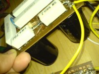
When you have a kit amp based on an unknown (to us) pcb design, wired with no dressing in a long distance on a plank, using wires and alligator clips going around, its futile to test it and decide that you are having a hum issue or not and due to what. It can be anything. Amps don't get tested or debugged like that. Put it together in some enclosure or tower in a comprehensive manner, so we can start following it. Assuming that the boards have no issues themselves, then some clear pictures in its final form can help us help you. I don't want to dissappoint you, but this is a very early, very hasty stage to draw conclusions about what you have there. Even if we solved it at this stage, it will be a totally different situation when you put it together in its final construction, and then another issue could arise. Take a picture of pcb's underside before you mount it, in case it is going to be useful when you finish the test build.
When you have a kit amp based on an unknown (to us) pcb design, wired with no dressing in a long distance on a plank, using wires and alligator clips going around, its futile to test it and decide that you are having a hum issue or not and due to what. It can be anything.
ahh i get it now. yes this was meant to be temporary. so i will proceed with the first build with the frames/permanent wiring and take go from there.
1 - have put in the 220k grid resistors on 6550 stage
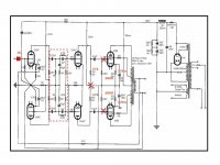
2 - trying to match the GE50 cct with the JA30. due to the complexity in the stage between AX (input) and AU (invertor) in GE50, a separate pcb with parts will have to be done and then wire patched into the main board (at cut sections) where applicable.
keep you posted thks.
 Good luck!
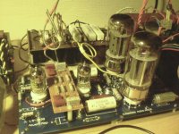
hi all, just finished the mod using the GEC50 cct given by Salas. now the board looks like below with a smaller board attached atop. the main objective is to reverse the AU and AX from the original ctt. amazingly, with properly soldered wires, GNDing and wire dressing, the humm has disappeard despite components mounted in very close proximity.
made some changes to suit the pcb tracks and also existing components.
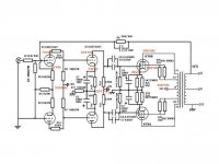
input stage : its now 12AX7 !!! B+ at 320Vdc. has an additional 1k ohm resistor on the incoming input line and all else is same.
invertor stage : its now 12AU7 !!! B+ at 327V, did not use the balance trim pot but used 2 matched 47k ohms resistor on the anode line to B+. all else is same.
power stage : same 6550 with B+ at 428V, cathode at 40V and screen at 425V. changed all resistors - 10k at grid not used but only a 220k, cathode resistor is 500ohms // 220uF cap and screen resistor is 100 ohms.
all components in the dotted red rectangle between the AX and AU are on the small pcb. the pcb is connected back to main board via short wires.
current problem : unable to crank up volume. there is music coming out but in very small volume level (very soft). the music is clear to a point and further volume incremental only distorts the whole thing. connecting the NFb resistor changes the sound to morse code like sound. pls help thks
made some changes to suit the pcb tracks and also existing components.
input stage : its now 12AX7 !!! B+ at 320Vdc. has an additional 1k ohm resistor on the incoming input line and all else is same.
invertor stage : its now 12AU7 !!! B+ at 327V, did not use the balance trim pot but used 2 matched 47k ohms resistor on the anode line to B+. all else is same.
power stage : same 6550 with B+ at 428V, cathode at 40V and screen at 425V. changed all resistors - 10k at grid not used but only a 220k, cathode resistor is 500ohms // 220uF cap and screen resistor is 100 ohms.
all components in the dotted red rectangle between the AX and AU are on the small pcb. the pcb is connected back to main board via short wires.
current problem : unable to crank up volume. there is music coming out but in very small volume level (very soft). the music is clear to a point and further volume incremental only distorts the whole thing. connecting the NFb resistor changes the sound to morse code like sound. pls help thks
Attachments
Last edited:
Sounds like you've got an oscillation. The "Morse code" sound may well be blocking distortion.
1. Get a scope. Working blind, your chances of getting a complex circuit working properly are minuscule. A good used 100MHz scope will cost you less than the output transformers. You're trying to fix a car without socket wrenches.
2. Did you remove the grid stopper resistors from the output stage? You have an X through them. If so, put them back in. They're there for a good reason. All stopper resistors should be tight to the grid pins.
3. Make a DC voltage map, i.e., measure the voltages to ground at all plates and cathodes to see if the basic circuit parameters are correct.
4. DC heaters are a waste of time in power amps. If the heater leads are tightly twisted and all else is right in the circuit, you'll be able to keep hum more than 90dB down.
5. Double-check that the feedback you're applying isn't accidentally positive.
hi SY,
2 - the X means the resistor is not there but the grid pin has a direct track connection to the 0.5uF. also it T's off to a 220k resistor and then GND. is this OK? just that it does not follow the actual cct. if the 10k must be there then the track must be cut to insert.
3 - i made a voltage map as suggested:
12AX7 B+320V - anode(top)=198V, cathode(top)=2V, anode(bott)=198V, cathode(bott)=2V.
12AU7 B+328V - anode(top)=149V, cathode(top)=5V, anode(bott)=148V, cathode(bott)=5V
6550 B+430V - anode(top)=423V, screen(top)=425V, cathode(top)=40V, anode(bott)=422V, screen(bott)=425V, cathode(bott)=40V
any abnormalities observed? the screen is higher than the anode in the 6550, is that OK/safe? datasheet says max 400V on screens.
4 - yes DC on 6550 is not needed.....agreed.
5 - lets leave nfb out for now till the basic problem is off.
just managed to wire up the 10k grid resistors on the 6550. no improvement on the sound, in fact the volume is even lower now than before. could it be the stage between the AX and AU? the previous design, the stages had been directly connected via tracks whereas the GEC cct has got couple of caps in that path. could they be open or something?
Rich, the jadis 30 cct has the order as 12AU7-12AX7-6550 whereas the GEC cct has the order as 12AX7-12AU7-6550. the jadis cct was deemed idiotic and unsafe by members hence im looking at converting the pcb into GEC cct. the conversion is done as you can see the last pic of it having a smaller board atop the main. just that i cant crank the volume up.
If the grid stoppers are affecting level at all, you might have a problem in the grid circuit of the output stage, or the tubes themselves might be bad (grid current). They're in series with a high impedance grid so should have close to zero effect on anything lower than RF. Any chance that the grid leaks are accidentally the wrong value?
got this working now. it probably was the signal pass caps from the AX into the AU. i got another board made out to replace and the problem is gone. got good powerful music now. thks for all the help.
now do i need to crank up the 6550 B+ to 500Vdc as suggested in original cct? would that bring any benefit? grid leak to GND is 220k and grid stopper is 10k. cathode at 40V.
also what happens if the 220uF bypass cap on cathode resistor be changed to 50uF in the cct?
thks
now do i need to crank up the 6550 B+ to 500Vdc as suggested in original cct? would that bring any benefit? grid leak to GND is 220k and grid stopper is 10k. cathode at 40V.
also what happens if the 220uF bypass cap on cathode resistor be changed to 50uF in the cct?
thks
now do i need to crank up the 6550 B+ to 500Vdc as suggested in original cct? would that bring any benefit? grid leak to GND is 220k and grid stopper is 10k. cathode at 40V.
also what happens if the 220uF bypass cap on cathode resistor be changed to 50uF in the cct?
thks
Not a good idea with 6550 in UL at 500V. I've done it and so have others have gotton away with it, but not the done thing. This tube is rated 470V+ in UL mode. You will also have to change the grid leak resistors to lower values. Stay with KT88's at 500V you will get 50W o/p.
Increasing the o/p stage cath decouplers to 220uF merely tailors the -6dB response to a lower frequency on the bode map; usually no problem unless LF instability appears. This depends on quality of o/tranny and amount of global nfb and interstage caps. In circuits like this, don't overdo them.
I presume you tacked on the negative feedback-.
richy
Not a good idea with 6550 in UL at 500V.
I presume you tacked on the negative feedback-.
richy
well thats what the original GEC 88-50 cct says - 500V B+ UL. im using the hammond 1650R so how much power you rekon the 430V B+, cathode biased 40V, im on now puts out?
yes there is NFB using a 510k ohm resistor. no caps.

how much power you rekon the 430V B+, cathode biased 40V, im on now puts out?
yes there is NFB using a 510k ohm resistor. no caps.
Down to Mullard power; 6550 tubes at 430V will give around 35W perhaps a tad more. The 510K nfb feedback res seems incorrect. Way too high. Have you misread it..for GEC design, should be around 5K1 for 20dB global nfb.
SY; my Sovtek 6550 in UL, the screen starts screaming red at 500V+;60mA cath Iquies. Perhaps a roapy tube.
richy
- Status
- This old topic is closed. If you want to reopen this topic, contact a moderator using the "Report Post" button.
- Home
- Amplifiers
- Tubes / Valves
- DC filaments for 6550s