Recently I encountered an interesting 6V6 push-pull amp in an archival issue of Audio Express. The circuit came from RCA tube manual RC-19. You can see it at http//mysite.du.edu/~etuttle/electron/elect35.htm (avoiding nasty copyright bullets..). The really interesting feature is the use of starved 6AU6 pentodes as drivers and what appears to be partial feedback. Looking at the circuit closely, I thought for sure that the 330k plate resistors on the 6AU6s were typos, but apparently this guy has actually constructed the amp per the schematic and had it work for him, as he puts operating voltages in the schematic he posted. I'm temped to try this type of circuit using a pair of 6U8s to replace the 12AU7 and 6AU6s. Comments? Has anyone else built this thing?
Last edited:
Well, there's feedback from the 6V6 outputs to the 6AU6 drivers, but no global feedback from output to input. I'm pretty much disregarding the 12AU7 input, as that's a real stardard circuit and of no great interest. The thing that interesting is the starved 6AU6s as drivers. The circuit looks like the results of a lot of "cut and try" bench work from some clever RCA engineer. There is also a big 7027A push-pull amp circuit in the back of my RCA manual that uses partial feedback. That one can be viewed at http://www.angelfire.com/vt/audio/rca50wdia.gif
Last edited:
Comments? Has anyone else built this thing?
I haven't built it, and I wouldn't waste my time. That design is hideous in more ways than one. Based on the figures given, the plate current through the 6AU6s is 336uA. (WTH is it with these people wanting to run small signal pents at ridiculously low plate currents anyway?) You've already got onehelluva problem right there: it's no where near enough current to charge up the Cgk + Cstray + Cmiller of the 6V6s, and that means a slew rate problem at the high frequencies. And let's not even discuss what happens when that inevitable fast rising transient hits the 6V6 control grids hard enough to drive them positive. Where's that grid current going to come from? They'll clip like transistors.
Why bother to use one of the better phase splitters, only to reintroduce phase-to-phase imbalance with two independent voltage amps that may not have the same gain? A differential second stage, whether with pents or triodes would preserve phase-to-phase balance.
35db(v) of NFB is just way too much. If you're gonna do that, just hop on over to the Solid State forum and build a transistor amp: cheaper, easier to build, non-potentially-lethal voltages to deal with, you don't need to make all those big holes in the chassis, no heater power worries. You won't be able to tell the difference anyway.
I question why 6V6s even need local NFB. This is already one of your better audio finals. All they require is a bit of gNFB to take the edge off, and get your speeks under control. If you have a VT design that needs more than about 12db(v) of gNFB, then your design is EFFFFFFFFFFFFFFFFed UP! Better to go back to the drawing board, rather than rely on gNFB to sweep your mistakes under the rug.
I don't believe the idgit that drew that schemo knew what he was doing.

Last edited:
I know there are a few people out there who are big fans of this circuit. If you are worried about drive capabilities, just rescale it for higher idle current on the 6AU6s, reduce the local feedback slightly, and add a global loop. I've been tempted to build a similar amp for a long time.
I know there are a few people out there who are big fans of this circuit.
There are also fans of Shakti Stones, C-37 goop, $11,000 Volume Controls, and other assorted audiophooleries.

If you are worried about drive capabilities, just rescale it for higher idle current on the 6AU6s, reduce the local feedback slightly, and add a global loop. I've been tempted to build a similar amp for a long time.
Even better: find a better design. There are lots of really good designs to be found right here.
Pentodes in pentode mode are quite forgiving with low Ia... they sound good with lower noise. Of course there are exceptions... EF184, EF86, etc. sound quite nice burning at 9mA")
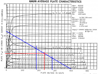
How do you even deal with something like that? The plate characteristics for the 6AU6 don't go that low. This loadline certainly doesn't look too bad, and it has the current reserve to slap around whatever grids you connect as the next stage, so no slew rate problems either.
Attachments
Miles, it's okay if you misunderstand the design The driver limitations are not a problem with a pentode output stage. And if you need to drive something more serious, you can easily bump up the idle current, reduce the plate load, and tweak the feedback. I bet the 50W version of this amp (linked above by wrenchone) would give a Citation II a run for its money.
Here is a link to a manual for an RCA amp based on this design: RCA SP-20.
The driver limitations are not a problem with a pentode output stage. And if you need to drive something more serious, you can easily bump up the idle current, reduce the plate load, and tweak the feedback. I bet the 50W version of this amp (linked above by wrenchone) would give a Citation II a run for its money. Here is a link to a manual for an RCA amp based on this design: RCA SP-20.
Miles, it's okay if you misunderstand the design
I understand it quite fine, thank you so very much.
From the 6V6 Spec sheet:
Crt= 0.7pF
Cgk= 9.0pF
Cpk= 7.5pF
From the text, the voltage gain of the 6V6s is 15:
Cmiller= Crt(1 + Av)= 0.7(1 + 15)= 11.2pF
Figuring a Cstray= 10pF (bare minimum if your lay-out is outstanding), then:
Ci= Cstray + Cgk + Cmiller= 10 + 9.0 + 11.2= 30.2pF
At 30KHz:
Xc= (2pi X 30E3 X 30.2E-12)^-1= -j175.7K
That's paralleled with a 330K DC grid return, so figuring the equivalent impedance:
G= 1 / 330E3= 3.03E-6
Bc= 1 / -j175.7E3= j5.69E-6
Y= 3.03E-6 + j5.69E-6
Z= 1/Y= 72.9E3 - j136.9E3
| Z |= 155.1K
Given the stated output, load resistance, and voltage gain, you need to swing the 6V6 grids 23.6Vp.
This gives:
Ip= 23.6 / 155.1E3= 0.152mAp
By the "Rule of Five", you need at least 0.76mA of plate current in the driver, and you have less than half of that. You will actually need quite a bit more, since you can not be sure how much stray capacitance you might actually have. This takes into account just the current you need to drive the input capacitance to avoid slewing. It does not account for clip behaviour when a transient comes along and attempts to take the control grids positive. That'll really make those 6AU6s roll over and die.
You've got a slew rate problem all right. Throw in poor clipping behaviour, grossly excessive NFB to make that clip behaviour even worse, and it's no wonder you have folks complaining in here that they bought a hollow state amp that sounded no better than a solid state amp. That thing is sure to have that great transistor sound.
The driver limitations are not a problem with a pentode output stage.
The simplistic explanation you see all the time, that Class A*1 finals just need voltage, not current, is just plain wrong. It doesn't take into consideration the fact that capacitance needs current to charge, and that the grids aren't going to see the true signal level until that input capacitance charges. Not enough charging current, and you'll get slewing at the high end: loss of detail, and your highs just won't sound right.
You still are missing both the context and the potential of the design, but hey, feel free to deprive yourself of clever circuits. This scales up wonderfully, and since this is DIY we are under no obligation to idle our 6AU6s at .4mA. Your analysis shows that it can make it to 20kHz, albeit while satisfying a more relaxed "Rule of Three", which I'll admit is a bit chintzy by today's standards. But 20kHz was likely the benchmark used by the designers in the very early 1950s, before there were many commercial Williamson amps to compete with for numbers and bandwidth. Change a few resistors and the above problems are solved. Add a balance pot, as with the 50W version, and there is even less to complain about.
Hi ,
I must confess to all , that since the first time I saw this design
I did not like it .
I apologize to all , if I am being more intuitive and less rational
but , definitely : I do not like this design .
I do not want to waste your time ( neither mine ) with mathe-
matical demonstrations , even because Miles Prower did it
with great clarity and knowledge .
First , I can say that the idea of a input stage ( voltage amp. )
made with a half 12AU7 runing 0.8 mA ( !!! ) , does not “ attract ”
me anyway .
Second , the idea of two separated drivers made with two 6AU6 ,
runing like pentodes , with NFB from 6V6 plates , looks very , very
strange , complicated and inefficient , only to say the less .
The phase inverter ( second half of 12AU7 ) and the output stage
6V6 , are conventional and no comments about them .
Summarizing : IMHO , I would not waste my time and my money
building it . The result do not worth the effort . I bet it !!
Carlos
Summarizing : IMHO , I would not waste my time and my money
building it . The result do not worth the effort . I bet it !!
Don't build this amp, but be careful to dismiss the topology. There are some interesting advantages to splitting the driver stage.
I've been planning a 6DQ6 amp with a similar approach (closer to the 50W version) and better tube operating point. I shelved it earlier this summer out of laziness, but the parts are mostly there so I'll get it together in the next 6-12 months and report back
You still are missing both the context and the potential of the design, but hey, feel free to deprive yourself of clever circuits.
In the first place, it isn't a "clever circuit". This is very run-of-the-mill. Secondly, I stay away from "clever" for clever's sake. The whole thing looks a lot less like "clever", and a lot more like "quick 'n' dirty". A differential gain stage after the cathodyne would be more like clever, and it would perform better. I'm not against giving something ususual a go. My last project included a cascoded (6BQ7s -- dual triodes with no audiophool pedigree) LTP phase splitter/gain stage. Took that directly from solid state practice. No idea how that would sound, but once built it sure did perform.
My whole design philosophy is completely different. I don't ignore the capacitance problem, and I am a big believer in adequate grid drive. I suppose that's my solid state heritage asserting itself. I'm also not against using solid state where I believe solid state will do the best job (Power supplies, active loads, source followers).
It's an OK design, but I can do better.
This isn't meant to be a fight, but I think I'm looking at the forest here while you're focusing on the 6AU6s, er, trees...
Replace the 6AU6s with higher-gm pentodes. Maybe a pair of 6BA8As or 6AW8As, using the triode sections for a gain+cathodyne. Bump the idle current up to respectable levels, and add a means to balance the signal. The separated driver stage provides some advantages, as you don't need to worry about mismatched screen currents or long/CCS tails, and can apply effective symmetric feedback without putting the driver stage out of the loop (i.e., e-linear or Schade style). Of course, one will likely want to reduce the local feedback to something more reasonable, then wrap a basic 6-12dB global loop around the whole thing.
This hardly seems "run-of-the-mill", as the RCAs are some of the only amps to use this approach. But I'm not paying any attention to the parts values here or operating points - I have no interest in building this exact circuit, and couldn't care much less about the designer's questionable standards for acceptable bandwidth. It's a neat approach that has some interesting advantages, and can be adapted for use today in various forms.

It's one more way to turn output pentodes into triodes without screen grid abuse, and no Miller capacitance increase. With parallel feedback by voltage from anodes of output tubes we need more current from drivers; in this case series feedback by voltage asks for more voltage swing from a phase splitter. I did not try this one, but why not? Especially, when output transformers are cheap.
- Status
- This old topic is closed. If you want to reopen this topic, contact a moderator using the "Report Post" button.
- Home
- Amplifiers
- Tubes / Valves
- 6V6 P-P Amp From RCA Manual RC-19