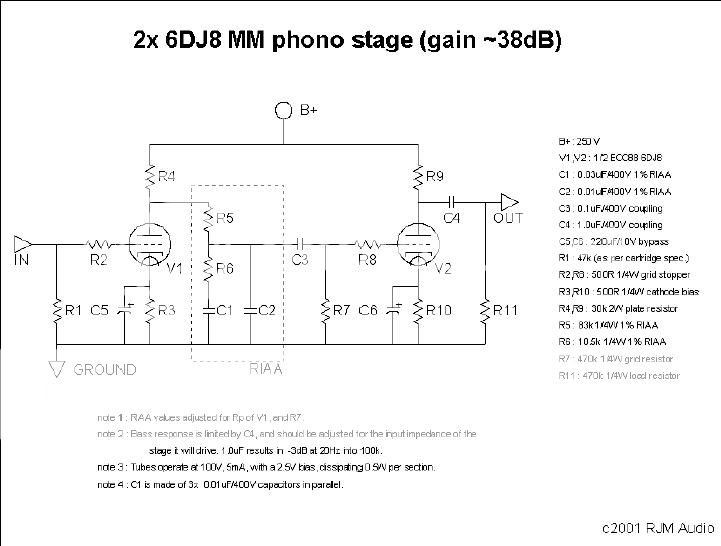
I made a PCB for the RJM phono stage to the attached schematic. I finally hooked everything up tonight and I get nothing, nada, bubkus...
I plugged the TT directly into the aikido and actually got a little noise with the volume all the way up. Plugged it back into the phono stage and nothing...
I am getting 237V B+, 87V at the plates, and about 2.3V off the cathodes. I followed all recommended values for caps and resistors. The one wierd thing is that one tube is drawing 7.2V for the heaters and the other one 5.6V. When I switch positions the wierd voltage follows the tube.
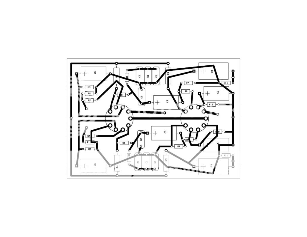
Attached is my PCB layout too...
1=plate2
2=grid2
3=cathode2
4=heater
5=heater
6=plate1
7=grid1
8=cathode1
9=IS
I looked over the PCB layout ad nauseum...please let me know if I am missing something truly obvious...
I plugged the TT directly into the aikido and actually got a little noise with the volume all the way up. Plugged it back into the phono stage and nothing...
I am getting 237V B+, 87V at the plates, and about 2.3V off the cathodes. I followed all recommended values for caps and resistors. The one wierd thing is that one tube is drawing 7.2V for the heaters and the other one 5.6V. When I switch positions the wierd voltage follows the tube.
Attached is my PCB layout too...
1=plate2
2=grid2
3=cathode2
4=heater
5=heater
6=plate1
7=grid1
8=cathode1
9=IS
I looked over the PCB layout ad nauseum...please let me know if I am missing something truly obvious...
Looking over the PC layout I don't see anything obviously wrong. However, since your tube filaments are in series and the voltages are not equal, the tubes filaments are drawing unequal currents. This causes unequal voltage across them. At least one of the tubes is defective. Maybe both. This could also explain the lack of sound. What tubes are you using? Better try some good quality tubes and 86 that imported garbage.
Should I measure idle or put a record on and measure?
Just measure the input without anything connected. I wanna know if the grid leaks on input load. DC there is not welcome. It can bias up the cart or even worse... Change the tube if you can find any.

...since your tube filaments are in series and the voltages are not equal, the tubes filaments are drawing unequal currents.
Magic filaments, or maybe they just would if they weren't in series?

I think your tubes are upside down.
Why would there be DC on the grid?
Can you measure any DC voltage across the phono input? If its there, it shouldn't. You would need to block with a capacitor.
Why would there be DC on the grid?
I think your tubes are upside down.
Why would there be DC on the grid?
I am afraid of non good tubes that leak, given the weird heater voltages mentioned they can be generally dodgy, so its better to know there is not some DC since there is no blocking input cap. It can mute or kill a cart if its enough. Just a simple check with the DVM is enough. If the tubes are upside down, of course all problems are explained.
Thanks for the input guys...I was hoping that the suggestions would lead to a tube swap...I acquired the tubes some time ago and thier origin is unknown...My fault I guess...
I just ordered a matched pair of 6DJ8/ECC88 JAN Sylvanias that should be here by the weekend...Being my first attempt at a PCB layout I wanted to make sure I did not overlook anything. My next project may be a point to point attempt. The PCB just helped me with the "flow" of the circuit as it were.
I just ordered a matched pair of 6DJ8/ECC88 JAN Sylvanias that should be here by the weekend...Being my first attempt at a PCB layout I wanted to make sure I did not overlook anything. My next project may be a point to point attempt. The PCB just helped me with the "flow" of the circuit as it were.
OK...a little update...I did a little tube rolling tonight to rule out bad tubes. I guess I should have done this before I ordered another pair. Anyways I put the 6CG7's from the Aikido into the phono pre and the 6DJ8s into the Aikido. In this room the typical source is the Zone 2 out from the TV room which funnels in XM radio from DirecTV.
I plugged the RCAs from the zone 2 into the input of the phono pre and voila...sound! However I need to turn the volume on the Aikido all the way up to max to even hear a reasonable amount of music. I plugged the zone 2 directly into the Aikido again with the suspect 6DJ8s and all was normal. The XM sounded great as usual - the 6DJ8s actually sound OK in the Aikido. Then I went and plugged the TT into the phono pre with the tubes still swapped. With the volume all the way up on the Aikido I could faintly hear the record.
I guess this tells me that the phono pre is severely dampening the signal coming into it - not amplifying.
I am now presuming that I have some resistors that are too high a value??? Any pointers as to what the obvious ones are to look at? I am thinking R2 and R8 maybe? I am still a rookie at circuits...
OK...a little update...I did a little tube rolling tonight to rule out bad tubes. I guess I should have done this before I ordered another pair. Anyways I put the 6CG7's from the Aikido into the phono pre and the 6DJ8s into the Aikido. In this room the typical source is the Zone 2 out from the TV room which funnels in XM radio from DirecTV.
I plugged the RCAs from the zone 2 into the input of the phono pre and voila...sound! However I need to turn the volume on the Aikido all the way up to max to even hear a reasonable amount of music. I plugged the zone 2 directly into the Aikido again with the suspect 6DJ8s and all was normal. The XM sounded great as usual - the 6DJ8s actually sound OK in the Aikido. Then I went and plugged the TT into the phono pre with the tubes still swapped. With the volume all the way up on the Aikido I could faintly hear the record.
I guess this tells me that the phono pre is severely dampening the signal coming into it - not amplifying.
I am now presuming that I have some resistors that are too high a value??? Any pointers as to what the obvious ones are to look at? I am thinking R2 and R8 maybe? I am still a rookie at circuits...
Why don't you follow SY's advice? And, measure all your resistor values too. While you are at it, inspect all your solder joints and measure continuity across the joints.
It baffles me why so many posters ask for help with a problem, without first doing the most basic measurements.
Sheldon
I am now presuming that I have some resistors that are too high a value?
Unlikely. Go do some voltage measurements- that will point to where the problem is so you can stop blindly guessing. I'll give you 5:1 that it's a wiring mistake.
Well thats why people come here Sheldon...to get advice on a problem with something that may be foreign to them. I do not live and breathe circuits and am still learning. I did check the voltages at the plate and cathode and they seemed to be within suggested values from the RJM circuit notes.
I could spend weeks trying to diagnose a problem with something I am just beginning to grasp and I would imagine that some of the folks here have encountered similar issues and would suggest ..."hey...doublecheck the voltage across R8 it should be X" or something
Or just plug away, guess randomly, and continue to baffle people.
SY, Sheldon,
It was stated which voltages exist where. Those could not be the case if tubes were 'upside down' or something was grossly out of kilter.
Cjkpkg,
From graphs for the ECC88 the anode voltage should be +95V and cathode voltage +2,5V, for an h.t. of +250V. Your measurements are close enough - which deepens the mystery.
But let me first explain about the different heater voltages. Background: At 6,3V the ECC88 draws 365mA heater current, while a special high quality version of this, the E88CC, draws 300mA. Now I recently happened to use two ECC88s (different makes), but lo and behold, one drew 300mA of heater current and the other one 365mA! I also used a series (dc) connection, and got just about the same voltage discrepancy as you.
I would therefore suggest that you check this - it would need a 6,3V supply and an AC meter. You could also measure the dc resistance of the heaters, but here I must not mislead you - that resistance would obviously be very low (cold heater). Still, I found 3,9 ohm for the E88CC and 3,2 ohm for the (real) ECC88. If your measurements come out to roughly the same, then you can differentiate between different -88s. Still, the hot measurement is obviously the better.
But back to the fact that you did get those electrode voltages even with this discrepancy, if I understood your first post correctly. Then as said, the mystery deepens and you will have to check the rest of the circuit. (I did not do that, accepting the other member's word on that.)
PS: As a temporary measure you could put a 39 ohm 5W resistor over the heater of the tube having the 7V across the heater, which should give about equal voltages there. But that is obviously not a healthy way out - next time you may put in a 'different' ECC88 etc.
- Status
- This old topic is closed. If you want to reopen this topic, contact a moderator using the "Report Post" button.
- Home
- Amplifiers
- Tubes / Valves
- phono stage woes...