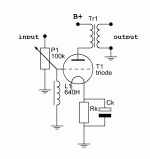
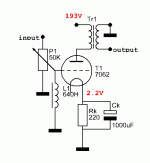
I replaced my 220K grid to ground resistors with grid chokes. 640 Henry with a listed 20 kOhm DCR, actual DCR 21.7K.
While I got less overall distortion I also lost some dynamics mainly impact and speed. I'm not sure what to do to get it back. I have an intermediate choke between the regulated supply and the amp board (this is a simple pre-amp) and I kept raising the henries on the choke which helped get some of the dynamics back but also made the bass more sloppy the higher I went. This is a choke with multiple taps so I can go from 10-30H in 5H steps.
Anyway. my concern is with the grid choke. Has anyone replacing resistors with a grid choke had a similar issue? If so what was the fix? I have a 1000uF cap on the bias.
While it's hard to be helpful without better info (schematic?) the place to start is the coupling cap ahead of the grid choke if AC coupled. Calculate the LC resonant frequency, better yet drop the values into LTspice and see what it's doing to the low end frequency response.
Its very simple. I'm using on half of a tube which is transformer output so there's only bias resistor 220R and the bias cap which is 1000uF. Pretty simple. I tried running without a grid to ground choke but lost all dynamics. I worked hard on voicing the circuit and the voltage (193VDC) and resistors mentioned above give the best sonic performance.
These are the chokes I bought http://cgi.ebay.com/ws/eBayISAPI.dl...617577&ssPageName=STRK:MEWNX:IT#ht_2423wt_884
Someone mentioned a good grid choke should have thousands of henries...
Silk has one but they're in Thailand.
These are the chokes I bought http://cgi.ebay.com/ws/eBayISAPI.dl...617577&ssPageName=STRK:MEWNX:IT#ht_2423wt_884
Someone mentioned a good grid choke should have thousands of henries...
Silk has one but they're in Thailand.
Things happening here are:
1) loading the driver tube (noticable)
2) applying a high pass filter (also noticable)
3) supplying grid current to the power tube (of minor importance)
@ #1: the plate resistor is paralleled by the grid leak resistor. Usually Rleak is 10 times larger than Rplate to have only marginal influence on the load.
@ #2: not until 117Hz your 640H grid choke equals the same Z as the grid leak resistor of 470K ohm.
When the inductive reactance of the grid choke becomes a dominant factor to the loading of your driver, a phase angle starts to turn up its head. To counteract the effect one could decrease Rplate, if one has margin in the amount of amplification.
The plate is loaded by the output transformer so I can only work with bias resistor/cap. Are you saying the OT may be what is needing to be helped in loading the tube? IE possibly this OT isn't loading the tube properly on its own? These are a pair of Audio Note double C-core I bought and there's no specs on them but I figured since its audio not they should have been built for something like a 5687 whereas I'm using a 7062 tube
If that is the circuit the low frequency response will vary by pot value and rotation.Ah, it's not about a power amp. Is this what you want to achieve?
-What kind of source has an output impedance of 1M?
When connecting an audio source to an amplifier or buffer stage we want to maximize voltage transfer.
To keep the signal from being loaded down, we keep Zload >> Zsource by a factor of 10.
See the attached example.
When connecting an audio source to an amplifier or buffer stage we want to maximize voltage transfer.
To keep the signal from being loaded down, we keep Zload >> Zsource by a factor of 10.
See the attached example.
Attachments
It can't be 1M I don't know why its measuring that way. I think its more likely 50K. Is there a proper way to measure the impedance beyond measuring the output jack?
Its an audio note dac I built up into a wholly different animal. I'll measure the resistors across on the output jacks.
I appreciate all your help. It makes sense.
Its an audio note dac I built up into a wholly different animal. I'll measure the resistors across on the output jacks.
I appreciate all your help. It makes sense.
If you can output an known voltage on a fixed resistor you can obtain the output impedance.
First try a coupling cap (100nF-1uF) between the DAC and the buffer pot. If not successful you can put a fixed resistor in series with the grid choke (47K-100K). See if this helps.
You probably load the DAC too much with the low Rdc of the grid choke because of its highish output impedance, but this is an assumption. A 100K or 200K pot would then be beneficial too.
BTW it's not appropriate to put a choke between the regulator and the buffer.
Pardon my ignorance. Are you calling the line output tubes the buffer?
Just so I understand correctly. Right now the choke follows the regulated supply then splits power to two diodes which feed two film cap and power for the amp board (buffer?) is fed that way. Kinds of a pseudo mono set up.
I'm running a 220K grid to ground resistor before putting the chokes in. If I put a resistor in series with the choke isn't that defeating the purpose of the choke?
Last edited:
Yes, I do. Sometimes the difference between a buffer and an amplifier is subtlePardon my ignorance. Are you calling the line output tubes the buffer?
According to some the name is derived from the amount of amplification it gives, while others name it after its function in the audio chain.
Try without the extra filters. If you are concerned with channel separation take two regulators. There will be a PCB soon for the Simplistic HV Shunt. maybe this afternoon.Right now the choke follows the regulated supply then splits power to two diodes which feed two film caps and power for the amp board (buffer?) is fed that way. Kinds of a pseudo mono set up.
Yes it is, but you get to know what the effect of loading is to your source. It might be necessary to revise the DAC if you want to try it on other amplifiers in the future.I'm running a 220K grid to ground resistor before putting the chokes in. If I put a resistor in series with the choke isn't that defeating the purpose of the choke?
I would say that using a grid choke post volume control pot makes no sense to me at all.
A resistor to protect against the pot wiper going open here is all that is required, and the higher the value the better. (Less interaction with the pot taper as a function of wiper position.)
You have created an unintended tone control circuit with this topology, one with a response that is strongly dependent on the position of the wiper. In addition your choke is not just an inductive reactance, but also has significant stray capacitance which will result in an HF roll-off, also dependent on the position of the pot. Worse still is the possibility that the inductor in conjunction with its stray capacitance, Cmiller and other strays has one or more resonances inside the audio frequency band.
Sorry this is a bad idea.
Grid chokes are ideal in situations where they are driven by a low fixed source impedance and the tube driven such as the 50 is intolerant of reasonable values of grid circuit resistance due to grid current. (Maximum grid circuit resistance for the 50 is only 10K, requiring IT drive, a grid choke or a very gnarly driver capable of swinging the required voltage into a 10K load.)
I'd save those chokes for a power amplifier project.
- Status
- This old topic is closed. If you want to reopen this topic, contact a moderator using the "Report Post" button.
- Home
- Amplifiers
- Tubes / Valves
- Issues with grid choke


