I would think that any time you start moving the screen voltage around, you lose efficiency. By that, I mean you will have to start dissipating power in the control grid to get the same maximum power.
I would be curious to see curves drawn for an e-linear setup and a plate-grid feedback setup with similar 'mu' target. I would bet that the simple plate-grid feedback would have higher max power without grid current. Would e-linear have some advantage as far a linearity goes? Unfortunately, I am still young and haven't had time to build a curve tracer yet.
So, I don't really know but am curious as well.
To first order, when pentode drivers are used and screens are connected to the taps, e-linear functions similarly to cathode feedback, since the feedback signal is seen by the grid and screen. But it has the advantage of not requiring a tertiary winding. Of course, you can also disconnect the screens and run the output stage in pentode - which I think has some appeal.
It is thus also similar to plate-to-grid feedback when UL connections are used for the screen, and requires the same added drive capability. Of course, it is a slightly less-flexible arrangement. I think the largest benefit over plate-to-grid feedback would be simple convenience and elimination of plate-to-grid resistors. I'm sure Douglas can provide further comment. Within limits of stability, something like the Citation II feedback scheme offers additional benefits since it includes the driver stage in the loop. But again, that's a higher effort approach, requiring more tweaking.
It is thus also similar to plate-to-grid feedback when UL connections are used for the screen, and requires the same added drive capability. Of course, it is a slightly less-flexible arrangement. I think the largest benefit over plate-to-grid feedback would be simple convenience and elimination of plate-to-grid resistors. I'm sure Douglas can provide further comment. Within limits of stability, something like the Citation II feedback scheme offers additional benefits since it includes the driver stage in the loop. But again, that's a higher effort approach, requiring more tweaking.
Last edited:
It's just old fashioned shunt feedback. Easier to do it with one resistor from output plate to previous plate, plus you can control the amount.
Leave the screen alone, all it does is increase distortion relative to any other configuration of equal gain (including triodes and UL). The control grid is the most linear input and has earned its name with good reason.
Tim
Leave the screen alone, all it does is increase distortion relative to any other configuration of equal gain (including triodes and UL). The control grid is the most linear input and has earned its name with good reason.
Tim
I just finally have taken the time to study Schade's 'Beam Power Tubes'. I painstakingly plotted points for KT88 curves in Excel and then calculated curves for various plate to grid feedback ratios. I was struck by the fact that I could get much better linearity than a 300B with a higher mu. The cherry on top was the fact that I could also get much higher plate currents without control grid current along the same load line. (more power output)
What I don't understand is why do ultralinear circuits exist? After my curve drawing exercise, it is apparent that I can have my cake and eat it too. (Well, I do have to provide a screen supply, I guess.) Why would we give up the benefits of the accelerating grid(at a constant voltage) if we don't have to? To save a few components in a feedback network and screen supply? Is there a gotcha that I don't know about yet? As I said, I'm still young and haven't had a chance to build a plate to grid feedback project yet.
The control grid is the most linear input and has earned its name with good reason.
What I don't understand is why do ultralinear circuits exist? After my curve drawing exercise, it is apparent that I can have my cake and eat it too. (Well, I do have to provide a screen supply, I guess.) Why would we give up the benefits of the accelerating grid(at a constant voltage) if we don't have to? To save a few components in a feedback network and screen supply? Is there a gotcha that I don't know about yet? As I said, I'm still young and haven't had a chance to build a plate to grid feedback project yet.
I just finally have taken the time to study Schade's 'Beam Power Tubes'. I painstakingly plotted points for KT88 curves in Excel and then calculated curves for various plate to grid feedback ratios. I was struck by the fact that I could get much better linearity than a 300B with a higher mu. The cherry on top was the fact that I could also get much higher plate currents without control grid current along the same load line. (more power output)
What I don't understand is why do ultralinear circuits exist? After my curve drawing exercise, it is apparent that I can have my cake and eat it too. (Well, I do have to provide a screen supply, I guess.) Why would we give up the benefits of the accelerating grid(at a constant voltage) if we don't have to? To save a few components in a feedback network and screen supply? Is there a gotcha that I don't know about yet? As I said, I'm still young and haven't had a chance to build a plate to grid feedback project yet.
Why do ultralinear circuits exist? -- Good question
A better question might be, why did the Hi-Fi world go with UL in such a big
way rather than the scheme the "inventors of the beam power tube" advocated?
Why is plate feedback not way more common?
One answer might be that Williamson and UL amplifier designs were successfully
marketed as solutions to the internal resistance problem of beam power tubes.
Behind this might be that O.H. Schade's reference design used an interstage
transformer to sum the local feedback with the grid signal. That wouldn't have
been super popular with manufacturers, leading to the marketing of alternate
designs.
I think this may have postponed the further development of O.H. Schade's
design, although there were a good number of O.H. Schade-style designs
through the years; I run across one now and then.
When did direct feedback to the driver plate show up?
I prefer low and stable like a rock voltage on a screen grid. Of course, in such case first grid bias must be regulated as well.
Yes, I think that's the approach.
Add local feedback and you have a nice triode. Adjust local feedback to optimize
mu and Rp for your circuit (gm=mu/Rp). A great shortcut for ballpark estimates
is to set the "mu" of the stage by adjusting the feedback, then calculate Rp by
mu/gm where you just use the tetrode gm for your Vg2... The error is that mu
and gain are not identical for triode power output stages.
I wonder how stable the high-gm tetrodes would be with well regulated g2 and
fixed g1. It "feels" like an additional balancer, e.g. servo, would be needed.
On a related subject, who has studied O.H. Schade's discussion of beam power
tubes vs. triodes for class AB operation? Pretty compelling if you work some
case studies. The gist is that tetrodes are more suited to AB than are low
impedance triodes, and that low impedance triodes are best run class B.
(well you need to remember they's selling beam power tubes here ;-) )
But I think the basic reasoning makes sense *especially* in the context of
local feedback across a class AB P-P stage. Constant gm across 2 tubes
through the crossover region, linearized by the local feedback.
Woulld a bifilar OPT be any advantage in a tetrode AB stage with local FB,
as it would in class B with triodes?
Michael
With Anode to Grid feedback the feedback resistor is effectively in parallel with the Miller Capacitance. This puts a definite upper limit on the size of resistor you can use and still maintain reasonable high frequency response.
In my Baby Huey I'm experimenting with Ultralinear PLUS screen to grid feedback. No definitive conclusions yet. Only listening so far, I need to make some measurements.
Cheers,
Ian
In my Baby Huey I'm experimenting with Ultralinear PLUS screen to grid feedback. No definitive conclusions yet. Only listening so far, I need to make some measurements.
Cheers,
Ian
With Anode to Grid feedback the feedback resistor is effectively in parallel with the Miller Capacitance. This puts a definite upper limit on the size of resistor you can use and still maintain reasonable high frequency response.
In my Baby Huey I'm experimenting with Ultralinear PLUS screen to grid feedback. No definitive conclusions yet. Only listening so far, I need to make some measurements.
Cheers,
Ian
I keep thinking that, then reminding myself that it's a tetrode, and the miller
capacitance is shielded internally by the screen grid. With UL, you will have
some miller effect due to g1-g2 capacitance but not if g2 is regulated.
So I think you also need to consider the miller effect with E-linear, however,
the lower signal voltage allows a lower value feedback resistor.
There still is an upper limit on the size of the feedback resistor due to other
capacitive coupling between anode and grid, but I think that's manageable
through careful wiring and layout.
I'm very interested in what you learn from these experiments. Should be a
real life evaluation of different local feedback techniques.
Cheers,
Michael
What I don't understand is why do ultralinear circuits exist?
The same reason there are over 150,000 posts in this forum: because it's "different". And like so many posts here, just because it's different doesn't mean it's any better.
Alas, since tube audio is a fashionable business, it follows the rules of fashion: whether or not something looks or measures or sounds* like crap, the rulers of what's fashionable will always insist that something novel sounds good, if for no other reason than, they *think* it sounds good.
*Sound quality based on double blind tests. (Incidentially, notice that flame wars have been started over blind testing, by Rulers of Fashion, because it is a method which threatens their position of power.)
Tim
I keep thinking that, then reminding myself that it's a tetrode, and the miller
capacitance is shielded internally by the screen grid. With UL, you will have
some miller effect due to g1-g2 capacitance but not if g2 is regulated.
So I think you also need to consider the miller effect with E-linear, however,
the lower signal voltage allows a lower value feedback resistor.
There still is an upper limit on the size of the feedback resistor due to other
capacitive coupling between anode and grid, but I think that's manageable
through careful wiring and layout.
There is still miller effect. Not as much, but it becomes significant under some circumstances. My class D tube amp requires a cathode follower to drive its sweep tube output because the ~2pF g1-p capacitance is significant when trying to swing it in 200 nanoseconds.
An externally hosted image should be here but it was not working when we last tested it.
This is the plate output waveform, 112kHz (2µs/div). As you can see, it's fairly crisp, with an edge of 100ns or so. That corresponds to a bandwidth on the order of 5MHz, far in excess of anything in audio. Indeed, this illustrates that you really don't need anything more than a 12AX7 to drive a 6L6! Sure it looks good to use more, but That's Not Engineering.
A plate-grid feedback resistor forms a zero with the miller capacitance. As such, you will have a DC-to-midband gain of R1*G / (R1 + R2*(G+1)), where G is gain, R1 is the feedback resistor and R2 is the source resistance. (Notice that, for small ratios of R1/R2 and large values of G, overall gain reduces to just R1/R2, which is what you learn about op-amps.) At frequencies approaching F = 1 / (2*pi*R1*Cm), gain starts dropping, and reaching unity gain ("fT") by F = 1 / (2*pi*Rth*Cm), where Rth is the Thevenin impedance R1 || R2.
Tim
There is still miller effect. Not as much, but it becomes significant under some circumstances. My class D tube amp requires a cathode follower to drive its sweep tube output because the ~2pF g1-p capacitance is significant when trying to swing it in 200 nanoseconds.
This is the plate output waveform, 112kHz (2µs/div). As you can see, it's fairly crisp, with an edge of 100ns or so. That corresponds to a bandwidth on the order of 5MHz, far in excess of anything in audio. Indeed, this illustrates that you really don't need anything more than a 12AX7 to drive a 6L6! Sure it looks good to use more, but That's Not Engineering.
A plate-grid feedback resistor forms a zero with the miller capacitance. As such, you will have a DC-to-midband gain of R1*G / (R1 + R2*(G+1)), where G is gain, R1 is the feedback resistor and R2 is the source resistance. (Notice that, for small ratios of R1/R2 and large values of G, overall gain reduces to just R1/R2, which is what you learn about op-amps.) At frequencies approaching F = 1 / (2*pi*R1*Cm), gain starts dropping, and reaching unity gain ("fT") by F = 1 / (2*pi*Rth*Cm), where Rth is the Thevenin impedance R1 || R2.
Tim
That's impressive! I found it tough to get MOSFETS to switch in 200 nS
without clobbering each other ;-)
Sure, Miller effect can be caused by any source of g1-p capacitive coupling,
so it never goes away completely. Nevertheless, I think you reinforced
my point that it can be dealt with through the proper attention. My current
tetrode-of-choice (4CX250) has about .04pF (Miller) feedback capacitance in
common cathode mode with fixed screen voltage. The wiring capacitance will
likely dominate.
So plate feedback requires attention to the feedback bandwidth to maintain
good unity gain BW and slew rate. This is less of a problem with E-linear and
not an issue with utlralinear? This is where a Schadeode differs from a true triode.
A good question may be; What unity gain bandwidth is enough to reduce TIM
distortion to acceptable levels? What slew rate is needed? You're showing
what must be >1000V/uS, assuming >100V P-P swing.
Cheers,
Michael
PS I didn't mean for the title of this thread to sound contentious "what good is
E-linear anyway" which I realize now could be inferred. I honestly would like
to understand the technical advantages and disadvantages. The Miller effect
seems to be a fundamental issue in the scalability of plate feedback, for
example, that ultralinear and E-linear can somewhat mitigate.
Last edited:
With local plate-to-grid (aka "partial") feedback, the more feedback being used, the more it limits the driver stage headroom.
This is an important consideration when running the driver off the same supply as the output stage. The driver will clip before it can drive the output tube to full power if too much of this type of feedback is used. So by using only %40 of the output stage voltage swing for feedback, the driver get's significantly more headroom.
It should also be noted, that with partial feedback, more isn't always better. Besides the headroom issue mentioned above, your distortion doesn't lower in a linear fashion in relation to the amount of feedback being applied. What happens is the output tube gets linearized, but the input tube is outside of the loop, just the load it sees will change. It becomes more of a harmonic distortion cancellation type of circumstance. There will be a specific feedback ratio where even-order harmonics are almost completely nulled. Any more or any less causes even harmonics to come back. In certain circumstances, particular partial feedback ratio's can even cause THD to be worse than no feedback at all. For single ended amps, it's a good idea to find the feedback ratio where 2nd harmonic is about 10dB higher than 3rd.This is about ideal if you still want it to sound like a SE amplifier but have less distortion than open loop. Though I have found tube rolling can significantly change measurements, which is why I no longer pursue plate to grid feedback.
It really becomes a balance of many factors and types of feedback. Pete Millet probably found the types and ratio's of feedback that he used to be the best balance for this project.
Last edited:
With local plate-to-grid (aka "partial") feedback, the more feedback being used, the more it limits the driver stage headroom.
That's why the driver has to be designed properly to drive low input resistance of the stage with parallel feedback.
Here is what I used in my Pyramid-VII -- feedback resistors from plates of GU-50 output tubes to plates of 6P15P driver tubes are 240K.
http://wavebourn.com/forum/download.php?id=119&f=7
With local plate-to-grid (aka "partial") feedback, the more feedback being used, the more it limits the driver stage headroom.
This is an important consideration when running the driver off the same supply as the output stage. The driver will clip before it can drive the output tube to full power if too much of this type of feedback is used. So by using only %40 of the output stage voltage swing for feedback, the driver get's significantly more headroom.
It should also be noted, that with partial feedback, more isn't always better. Besides the headroom issue mentioned above, your distortion doesn't lower in a linear fashion in relation to the amount of feedback being applied. What happens is the output tube gets linearized, but the input tube is outside of the loop, just the load it sees will change. It becomes more of a harmonic distortion cancellation type of circumstance. There will be a specific feedback ratio where even-order harmonics are almost completely nulled. Any more or any less causes even harmonics to come back. In certain circumstances, particular partial feedback ratio's can even cause THD to be worse than no feedback at all. For single ended amps, it's a good idea to find the feedback ratio where 2nd harmonic is about 10dB higher than 3rd.This is about ideal if you still want it to sound like a SE amplifier but have less distortion than open loop. Though I have found tube rolling can significantly change measurements, which is why I no longer pursue plate to grid feedback.
It really becomes a balance of many factors and types of feedback. Pete Millet probably found the types and ratio's of feedback that he used to be the best balance for this project.
Agreed, and thanks for the information. Isn't 40% a lot of feedback? I was
getting into that territory though in order to get an equivalent 500 ohm
Rp using a low-gm (4500) beam tetrode. I needed higher voltage on the
driver than on the output, so yeah, been there decided no to do that...
I concluded I simply need more gm to use the OPT I had in mind at the
output power level I want. 10,000 gm (10mA/V) tubes help a lot!
With series feedback, the drive voltage needed would be the same as needed
by a triode of equivalent mu and Rp, all else being equal. If you're comparing
it to loop feedback, then sure, it's a big difference in drive requirement.
With shunt feedback, the drive voltage is not a problem. Shunt feedback to a
pentode driver with a high-gm output tube is the road I'm now on. I'm using
a high-gm driver also to enable a low-impedance shunt feedback path.
For me, it's not simply a matter of applying feedback to reduce distortion.
The amount of feedback needed is more a function of desired mu and Rp in
the overall design, at least with the design constraints I am working to.
But then there is the issue of distortion. The output tube gm is still nonlinear
which introduces a first order nonlinearity in the shunt feedback. The driver
has it's nonlinearity which combines.
I'd be interested in what circuit you used and how the distortion was impacted
by tube rolling. I suppose each tube has a little different transfer function
linearity in a particular circuit, leading to a different distortion profile.
Michael
Feedback is feedback is feedback. Not much you can change about that. Local, interstage and global feedback all have the same general behavior. The difference is basically phase, because local feedback is essentially foolproof, while global feedback needs compensation for the loop's phase shift.
Generic amplifier parameters are fT and open loop gain. The gain-bandwidth product defines how much gain and how much bandwidth your stage can yield. An op-amp with G = 1e5 (a fairly typical 100dB) and fT = 10MHz can be used for a gain of 10 up to 1MHz, or 100 up to 100kHz, etc. Compensation is a single dominant pole, so gain and bandwidth are proportional. This isn't of much importance in audio (as long as you don't use a 741, anyway), but is important around high-gain amplifiers, oscilloscopes, etc.
Notice that the roll-off point, where open loop gain falls 3dB, is very low: under 100Hz. This is of no consequence, because no one needs 100dB of gain; feedback keeps it flat.
For lower-gain stages, like we have here, the roll-off point is much higher and much closer to fT. Without feedback, miller capacitance rolls off at 1 / (2*pi*R*Cm), where R is Zin or Zout, whichever is higher (hmm, it should probably be both in series?). For a 12AU7 driven from a voltage source, Cgp = 1.5pF, G = 17 and Rp = 6.2k, so Cm = 25pF and f3 = 1MHz. (This represents a CCS-loaded stage; a resistor-coupled stage will have lower Zo because the load resistance is in parallel with plate resistance. Source impedance is also in series, so a weak driver (like a 12AX7, Zo = 60kohms or so) will drop bandwidth quite a bit -- hence most audio preamps roll off in the 100kHz band.) fT is roughly f3 * G, or 17MHz. If feedback is applied to this stage, gain falls and bandwidth (that is, f3) rises proportionally. If unity gain is desired (it's still an inverting stage, and Zo is probably lower, so this is not a useless step!), bandwidth is maximized, out to 17MHz.
Remember that feedback increases bandwidth and reduces distortion, at the expense of gain. Global feedback usually needs compensation, so it cannot be used to improve bandwidth as dramatically as local feedback. However, for the same reason, it keeps overall phase shift low in the passband, which might be desirable.
Tim
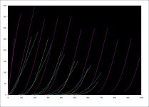
In case anyone is interested, here are the curves I was referring to in an earlier post. Blue is a KT88 triode connected with curves every 16V. Yellow is a 300B with curves every 30V. Pink is KT88 with 20% plate to grid feedback, curves every 20V. Well, The first curve is -10, the second is -20 and the rest are spaced 20V apart.
I'd like to build this and see how it sounds but don't know what value to pick for a feedback resistor. The current setup has a source follower driver, so I will just add a series resistor to define the output impedance of the driver and set the feedback ratio. Anybody have advice for me on where I should start?
I'd like to build this and see how it sounds but don't know what value to pick for a feedback resistor. The current setup has a source follower driver, so I will just add a series resistor to define the output impedance of the driver and set the feedback ratio. Anybody have advice for me on where I should start?
Attachments
Pick values large enough that they don't load either circuit appreciably (maybe 10 * R_L of the output?), small enough they don't cut into bandwidth too much (grid input capacitance is your enemy here) and small enough to satisfy grid leakage spec. The ratio can be found from the equation,
Av = R1*G / (R1 + R2*(G+1))
As you can see from the curves, such a connection has far lower impedance and much greater linearity than any comparable triode. Distortion and output impedance will be lower.
Tim
Av = R1*G / (R1 + R2*(G+1))
As you can see from the curves, such a connection has far lower impedance and much greater linearity than any comparable triode. Distortion and output impedance will be lower.
Tim
- Status
- This old topic is closed. If you want to reopen this topic, contact a moderator using the "Report Post" button.
- Home
- Amplifiers
- Tubes / Valves
- What's the advantage of E-linear