Recently I got myself into tube preamp upgrading “business”. To start with promising base, I choose the Counterpoint SA-7.1 preamp, found it, bought it, and, finally, received it a few days ago. I’ve read all threads here regarding this preamp, so I have some ideas what to do.
But here is a question: After initial listening I found that my preamp has a big rollover in frequencies greater than 12 KHz in the line stage.
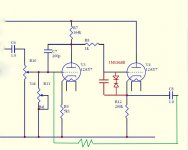
After studying schematics (for comparison I used schematics posted here:
http://www.diyaudio.com/forums/showthread.php?s=&threadid=38370&perpage=25&pagenumber=2), I found that my SA-7.1 rev. B has two Zener diodes 1N5368 B in series, cathode to cathode, in parallel with some capacitor connected between grid and cathode in the follower stage. See attached portion of schematics in red.
So, could it be original (looks like that)? Do I need it? My guess that capacitor was added to fix “troublesome cathode-follower (it likes to whistle)” how Michael Elliott put it. Could somebody give me an advice?
Second, I want to try a little bit of negative feedback to kill this gain and improve THD.
Initial idea was something like resistor in green on schematics. Do I need it to be more sophisticated?
Any input would be highly appreciated.
But here is a question: After initial listening I found that my preamp has a big rollover in frequencies greater than 12 KHz in the line stage.
After studying schematics (for comparison I used schematics posted here:
http://www.diyaudio.com/forums/showthread.php?s=&threadid=38370&perpage=25&pagenumber=2), I found that my SA-7.1 rev. B has two Zener diodes 1N5368 B in series, cathode to cathode, in parallel with some capacitor connected between grid and cathode in the follower stage. See attached portion of schematics in red.
So, could it be original (looks like that)? Do I need it? My guess that capacitor was added to fix “troublesome cathode-follower (it likes to whistle)” how Michael Elliott put it. Could somebody give me an advice?
Second, I want to try a little bit of negative feedback to kill this gain and improve THD.
Initial idea was something like resistor in green on schematics. Do I need it to be more sophisticated?
Any input would be highly appreciated.
Attachments
With the two zeners you have the forward-drop of one diode and the zener-voltage of the other diode in series. One single diode will reduce the positive grid voltage to 0,6V.
I see no reason not to get rid of the capacitor. If V4 oscillates increase the value of the gridstopper...
I see no reason not to get rid of the capacitor. If V4 oscillates increase the value of the gridstopper...
I see, it make sense, thank you.
What about global negative feedback schematics? (I don't want to discuss is it good or bad, just want to try and see the difference).
I couldn't find a good working example of such shematics on the web. There are plenty for the three tubes line stage, like in ARC SP-66, but no for the two tubes case as in SA-7.
Greetings!
I'm a noob here and have been lurking around the forum looking for infos on modifying the SA-7.1. Any updates on this thread?
Bump.
- Status
- This old topic is closed. If you want to reopen this topic, contact a moderator using the "Report Post" button.
- Home
- Amplifiers
- Tubes / Valves
- Another Counterpoint SA-7.1 question