Hi, first post here. Nice to be surrounded by knowledgeable people! 
Just purchased an EICO 666 in very good shape. Like many, I'm VERY confused with the different tube charts. Hopefully someone is willing to share his findings with the rest of us.
Basically I'll use it to test the tubes in my amp, namely the 12AT7, 12AX7 and EL34.
Has anyone been able to nail the definitive levers' settings for these tubes?
Any help will be good help!
Dan

Just purchased an EICO 666 in very good shape. Like many, I'm VERY confused with the different tube charts. Hopefully someone is willing to share his findings with the rest of us.
Basically I'll use it to test the tubes in my amp, namely the 12AT7, 12AX7 and EL34.
Has anyone been able to nail the definitive levers' settings for these tubes?
Any help will be good help!

Dan
The 666 had many different versions of the roll chart, and often there are significant differences between versions. Some charts contain settings which are just flat out wrong. I usually refer to the Coletronics chart for the 666 as a starting point, but I also check the settings as shown in the Eico charts too. You can find the Coletronics chart in the archives that Ian mentioned above.
http://bama.edebris.com/manuals/eico/666/charts-1978
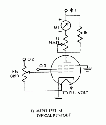
It's useful to spend some time with the 666 and understand what the levers do. The first nine levers are for the socket pins. Lever one goes to pin one, and so on. After that is the C lever, which goes to the cap lead. Obviously, if you are testing a tube in a type of socket which has fewer than nine pins, some of the levers serve no purpose. Each of these levers can be placed in one of six positions. It is useful to get a copy of the datasheet for your tube. Then you can verify the lever for each pin is set to a reasonable position.

Good luck. The 666 isn't a bad tester for what it does, especially once you begin to understand how the controls work. Make sure you also grab a copy of the manual and read over it several times. They explain how the circuit works much better than I've managed to do here.
http://bama.edebris.com/manuals/eico/666/charts-1978
It's useful to spend some time with the 666 and understand what the levers do. The first nine levers are for the socket pins. Lever one goes to pin one, and so on. After that is the C lever, which goes to the cap lead. Obviously, if you are testing a tube in a type of socket which has fewer than nine pins, some of the levers serve no purpose. Each of these levers can be placed in one of six positions. It is useful to get a copy of the datasheet for your tube. Then you can verify the lever for each pin is set to a reasonable position.
- 6 - open circuit
- 5 - grid voltage
- 4 - plate voltage
- 3 - screen voltage
- 2 - filament voltage
- 1 - ground
- 4 - plate=180V, screen=90V, grid=0~45V
- 3 - plate=180V, screen=90V, grid=0~15V
- 2 - plate=90V, screen=45V, grid=0~15V
- 1 - plate=45V, screen=15V, grid=0~5V

Good luck. The 666 isn't a bad tester for what it does, especially once you begin to understand how the controls work. Make sure you also grab a copy of the manual and read over it several times. They explain how the circuit works much better than I've managed to do here.
Here's another "must read" page for owner's of the venerable 666.
http://www.tone-lizard.com/Eico666.html
http://www.tone-lizard.com/Eico666.html
Dragging this thread back to the surface, two questions...
Has anyone published decent corrected settings for the 12A*7 series of tubes, settings that don't overload the plate?
The manual says many contradictory things. It says dual triodes should be tested with voltage applied to both sections of the tube, and shows schematics for that mode. They boast of the speed of testing. Then the charts show to do every section separately! It would seem the lever settings should be 4511245 661111 (for the 12AX7 and the 667 model tester), though I'm not exactly clear on how the buttons get pushed and what leakage tests would be made.
Can anybody clarify this stuff?
- Status
- This old topic is closed. If you want to reopen this topic, contact a moderator using the "Report Post" button.