Folks, I'm scratchbuilding a PP amp and have settled on a 6CG7 (9 pin 6SN7 equivalent) as my input and splitter stages.
I've got a 100k switched attenuator at the front end and want to configure half of the 6SN7 as a gain stage cap coupled to the second half as a concertina splitter.
The load being fed is a triode connected PP set of el84's in fixed bias.
B+ at the power stage is about 310v. Supply has a good 40mA of spare current to play with. I'll be dropping it down a bit further to feed the input and splitter stages which will be cap coupled to each other with a 0.47uF cap.
Any suggested operating points and component values for the input and concertina?
TIA
Drew
6-10mA should do. If you're not using feedback, I'd use a CCS for the first stage plate load, LED bias in the cathodes (2 red LEDs will get you 3.4V, which is a good value for an 8mA CCS). Assuming direct coupling, the concertina will be a bit trickier unless you have a lot of B+ available, since the first stage will run about 160-170V on the plate. If you've got plenty of B+ (450V or so), 15k resistors will work well.
If you capacitor couple, you'll have to carefully watch LF stability. You'll still need 450V for the concertina with a 6SN7 to get reasonably low source impedance and good linearity with the high input capacitance of the triode output stage- IMO, there are better tubes to use in this spot.
Pay close attention to heater-cathode voltage ratings!
I also would be very interested in the replies, as I have planned a single 6SN7 input/concertina into a PP 6L6GC.
I also plan to have no FB...and LED bias on the front 1/2 6SN7?
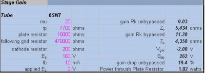
Here is what I have so far for the front 1/2 6SN7...gain of about 9 unbypassed, a little less after the concertina phase splitter.
A red LED should work perfectly for the 2 volts on Cathode to get 10ma with 262 V B+ and 160V on plate.
The only thing I don't know is if ithis arrangement will adequately drive a 6L6GC pair...
I also plan to have no FB...and LED bias on the front 1/2 6SN7?
Here is what I have so far for the front 1/2 6SN7...gain of about 9 unbypassed, a little less after the concertina phase splitter.
A red LED should work perfectly for the 2 volts on Cathode to get 10ma with 262 V B+ and 160V on plate.
The only thing I don't know is if ithis arrangement will adequately drive a 6L6GC pair...
Attachments
Sy, B+ is limited to about 300v.
Prefer for first attempt to do it the old way with resistors and caps on the cathodes than go the LED route.
Will cap couple the two sections rather than direct coupling for starters.
Once I've got my head around things better and if I decide I need gains then I'll start messing with it, but for starters would rather keep things simple.
John,Here is what I have so far for the front 1/2 6SN7...gain of about 9 unbypassed, a little less after the concertina phase splitter.
If you are using an LED, consider it bypassed for the sake of gain calculation. Or if you can, calculate it with the 4 to 8 ohm dynamic resistance of the LED. I think you will find it closer to 15 than 9.
")
Doug
Sy, B+ is limited to about 300v.
Then a 6SN7 for the concertina is probably not your best choice. An ECC88 will do better. (plug alert!) You might consider copying the ImPasse preamp circuit as your input stage.
At 300V with 15k anode and cathode resistors, the 6SN7 will give you about 100Vp-p from each output no sweat. Obviously you will get somewhat better linearity by using larger load resistors, but at least you know it is capable of driving a typical pair of 6L6GCs. Then it's just a question of how much input gain you think you need to get you to full output.john65b said:
The only thing I don't know is if ithis arrangement will adequately drive a 6L6GC pair...
At 300V with 15k anode and cathode resistors, the 6SN7 will give you about 100Vp-p from each output no sweat.
Depends on the stage current. To drive triodes with reasonable bandwidth, the current has to be relatively hefty. That means large drops across those resistors. Larger load resistors and the consequent lower current are a liability when trying to drive the high input capacitance of triodes at high frequencies.
What's the input capacitance of the output stage? Where do you want the HF rolloff at that point to be? What current does it take to achieve that bandwidth? How much standing current in the phase splitter will it take to provide that drive current without greatly increasing HF distortion?
You're ignoring that vital aspect here.
You're ignoring that vital aspect here.
I assumed he was running the 6L6s as tetrode, in which case there's practically no current demand. (Even with triodes, a concertina gives pretty good bandwidth into relatively heavy capacitative loads.)SY said:
Depends on the stage current. To drive triodes with reasonable bandwidth, the current has to be relatively hefty. That means large drops across those resistors. Larger load resistors and the consequent lower current are a liability when trying to drive the high input capacitance of triodes at high frequencies.
The load being fed is a triode connected PP set of el84's in fixed bias.
Small-signal bandwidth is important, but not the entire picture. For low distortion, you want to be running a decade higher current than you need to charge the output stage capacitance at the highest frequency of interest (no slewing allowed!). That's pretty straightforward to calculate.
Sy, am I right in my understanding that LED biased tubes don't require a cathode bypass cap?
(in other words, draw the load line, pick the operating point, plate resistor, select LED's to provide suitable forward volt drop to bias to that point, give it a grid leak and away you go...)
(in other words, draw the load line, pick the operating point, plate resistor, select LED's to provide suitable forward volt drop to bias to that point, give it a grid leak and away you go...)
- Status
- This old topic is closed. If you want to reopen this topic, contact a moderator using the "Report Post" button.
- Home
- Amplifiers
- Tubes / Valves
- 6SN7 operating points input gain stage and concertina