Can the Futterman style design for the 6AS7 be modified to use other tubes? if so what types?
What is the plate impedance of the 6N6P? 68 ohm? Is the symbol Ri for plate impedance?
I like the simplicity of the Futterman design and would be interested in experimenting.
What is the plate impedance of the 6N6P? 68 ohm? Is the symbol Ri for plate impedance?
I like the simplicity of the Futterman design and would be interested in experimenting.
Attachments
Based on prior experience I would say your +/- 60V supplies are a bit too low, something on the order of +/- 100V - 120V is more likely the case. The Russian made equivalent of the 6AS7 works very well in OTL amps.
The symbol for plate resistance is rp, but don't be misled as there are other losses in the tube that are not directly reflected by the plate resistance such as limited emission, etc., that come into play particularly at high plate currents.
The 6C33, 6336A/B/C are also good choices and a single one of either will comfortably replace a pair of 6AS7..
Rather than substituting different types in this design I would build the basic design, learn how it works and then perhaps build another using more exotic types.
Note that I would not necessarily recommend an OTL as a first tube project which I suspect this might be. They look simple on the surface but getting them reliable and safe is an arcane art not easily mastered by a newbie.
The output stages require the same sort of power supply capability current wise as a solid state amplifier, but at much higher voltages to account for the voltage drops in the output tubes under load. Several amperes can be required for reasonable output power levels and it has to be well filtered as well because the design has mediocre PSRR - this gets very expensive.
Building a proven design as intended is a much safer bet.
Hi Kevin,
Thks for the info. Yes 60V did seem awfully low for the plate voltages in this design.
It will be my third tube project. I have built one liestage and one headphone amp up to date now but yes relatively a newbie you could say.
I was considering this type of amp due to the non-existent supply of OPT's here in Uruguay and mission impossible of importing any.
Cuba like customs
Custom built is the only option, I think there is only one guy in this country who 'may' be able to construct an OPT but I doubt he's had much experience of this. I know he can build good power supply trannies though.
Let me read further into this. Wish there were more hours in the day.
Brit01 said:Can the Futterman style design for the 6AS7 be modified to use other tubes? if so what types?
Sweep tubes were used by old man Futterman near the end in the OTL 1 and OTL 3. They are very complicated designs and I'm told they could be "oscillating devils", perhaps because of the gain in the tubes. They were manufactured on PC boards, not hand wired. I would not recommend these even to experienced builders. You can find the schematics at the link below.
http://www.freeinfosociety.com/electronics/schempage.php?cat=1
Hi,
Maybe a dumb question awaiting a very good answer:
If getting impedance down to a low level has always been a challenge in these OTL designs would it be feasible to build one of these amps to drive a line array speaker with small speakers wired in series to create a high impedance for the amp?
Maybe a dumb question awaiting a very good answer:
If getting impedance down to a low level has always been a challenge in these OTL designs would it be feasible to build one of these amps to drive a line array speaker with small speakers wired in series to create a high impedance for the amp?
Then this sounds like an interesting project.
A whole bunch of cheap small cones as a line array project wired up in series to match the impedence of an OTL.
Thinking about small 3 or 4 inch speakers in a slim mdf case.
10 x 8 ohm speakers at 80 ohms in total.
OTL designed for 80 ohms per channel without feedback.
A whole bunch of cheap small cones as a line array project wired up in series to match the impedence of an OTL.
Thinking about small 3 or 4 inch speakers in a slim mdf case.
10 x 8 ohm speakers at 80 ohms in total.
OTL designed for 80 ohms per channel without feedback.
Making an OLT amplifier is a project I've had on the back burner for quite a while as I have plenty of suitable tubes on hand. Just no free time in quanity. These include 6528s, 6336A/Bs, 6394s, (26V 6336A) and some Bendix carbon plate 6082s (26V 6080).
As long as the amplifier's output remains balanced, all is fine. But any OTL amplifier, be it Circlotron or totem pole, exposes ones speakers to the risk of high DC voltage should a tube fail or short and offset the output. I personally consider Chinese tubes to be the least desirable in terms of reliability and trustworthiness. (sorry about that)
For this reason, unless you have cheap speakers that can be easily replaced, I would consider some form of fail-safe protection circuitry. Fusing the output at minimum. Or perhaps monitoring the current of each output tube (across a small resistor) with a comparator IC driving a transistor stage(s) to activate (or deactivate) a relay in series with the speaker output. Just food for thought.
Take a look at Bruce Rozenblit's web sit . www.transcendentsound.com
He sells very good sounding OTL kits. Much better way for some with little design experiance. He is in his second generation of the designs.
He sells very good sounding OTL kits. Much better way for some with little design experiance. He is in his second generation of the designs.
For this reason, unless you have cheap speakers that can be easily replaced, I would consider some form of fail-safe protection circuitry. Fusing the output at minimum. Or perhaps monitoring the current of each output tube (across a small resistor) with a comparator IC driving a transistor stage(s) to activate (or deactivate) a relay in series with the speaker output. Just food for thought.
Certainly good advice. Relays would be excellent, my Carver power amp has these as it is a bit of a beast pumping out 380 watts per channel at 8 ohms. These work very well.
Also fast blow fuses.
But if I was to build an OTL it would be a low powered unit to drive some home made line arrays for mid/upper range. Cones in the price range of 3-5 USD
")
I could use my SS Carver to drive the low frequencies from a valve preamp (it sounds magical with my current Aikido linestage) and the OTL to drive the line arrays.
I like this idea very much.
When the data states that the Anode dissipation (on each triode), is 4 Watts, is this referring to the output power? Or is it the grid dissipation (0.3W)?
Looking at the 6N6P (which I happen to have 10 and sound great) have a very low resistance of 68 ohms.
Could a number of these be used in a small OTL design?
Looking at the 6N6P (which I happen to have 10 and sound great) have a very low resistance of 68 ohms.
Could a number of these be used in a small OTL design?
Brit01 said:When the data states that the Anode dissipation (on each triode), is 4 Watts, is this referring to the output power? Or is it the grid dissipation (0.3W)?
Anode dissipation refers to the DC input power supplied. Plate voltage x plate current = watts dissipated by the plate. Anode means plate, not grid. Sorry, I have no experience with Russian or Chinese tubes and don't know that number without looking it up.
Thanks for the clarification.
Another good explanation:
Cathode voltage (cathode pin to ground) divided by cathode resistor value in ohms multiplied by HT voltage (anode pin to ground) minus cathode voltage.
A recent amp I just built with 6N6P has a anode voltage of 220V, cathode to ground voltage of 4V and cathode resistor of 200 ohms.
4/200* (200-4) = 3.92 watts.
This is quite a good number for a little triode with very low plate resistance.
The 6N6P tube has a Rp of 1.8kohm, not 68 ohm, 68 ohm is the cathode resistor value for typical operation, see here http://www.mif.pg.gda.pl/homepages/frank/sheets/113/6/6N6P.pdf
2 requirements that must be met by tubes in an OTL are low enough output impedance and to be able to handle high peak currents.
the output impedance for the inverted Futterman that is shown in the schematic has an output impedance which is Rp/(2(1+µ)) so with 6N6P we would get 1800/(2*(1+22)) which is 39 ohm, if we connect a few in parallel we could reduce this to a reasonable value that could be lowered even further by feedback.
The 2nd requirement is more difficult to fulfill, 6N6P have a max allowed anode current of 45mA and if we don't want to exceed that in operation it would give us very low output power.
For a push-pull OTL that works in class AB the average current of each tube is the peak current divided by PI so for 45mA average we would get a peak current of 141 mA, this would give an output power of ~80mW in 8 ohm. Doubling the number of output tubes would increase the utput power by 4 times and so on...
6N6P is therefore not a good choice for an OTL, 6080 variants are OK, 6C33C is better as with this tube you don't need more than 2 to get useable output power, (25W in 8 ohm).
Parallel connection of output tubes can give a lot of problems and should IMHO be avoided if possible, therefore the 6C33C is probably the best alternative for an OTL today
I do believe the 68 ohms is the subjested cathode resistor
and the plate resistance is 1.8K . By the way the circuite
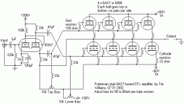
you posted is not the Futterman it is the tecknics sp? variation
of the futterman. In the Futterman the top plate resistor
of the phase inveter goes to the top output tube and the
cathode resistor in the phase inverter goes to the botom
output tube. And as posted that circuite will have a verry
high output impedience.
and the plate resistance is 1.8K . By the way the circuite
you posted is not the Futterman it is the tecknics sp? variation
of the futterman. In the Futterman the top plate resistor
of the phase inveter goes to the top output tube and the
cathode resistor in the phase inverter goes to the botom
output tube. And as posted that circuite will have a verry
high output impedience.
By the way the circuite you posted is not the Futterman it is the tecknics sp? variation of the futterman
Yes as I wrote it is an inverted Futterman described in the schematic.
In the standard Futterman both tubes work as if they where cathode grounded and the output impedance is Rp/2
In the inverted version both tubes as if they where cathode followers and the output impedance and is Rp/(2*(1+µ))
And as posted that circuit will have a very high output impedance.
No, this circuit gives lowest possible output impedance of any Futterman variation, however I would change the value of the cathode resistors that should be in the order of few ohms.
You , as i did, can read here and there many horrible stories about dead loudspeakers by an OTLamp ... I have built my first one 22 years ago , i rebuild it 10 years ago , i built 2 monster (10 tubes each) monoblocks 2 years ago and so on .... only with 6080 :
- 24 hours preageing for NOS ones
- testing and metering NOS and used ones to get pairs
- never going higher than 140 volts B+ and B- rail
- securing the bias rails with dual grid leak and pot resistors
I have never met any "BUMP" or "CRACK", POP from my beloved Altec 515 8G
Pierre
PICS of the monsters are on the forum ...
- 24 hours preageing for NOS ones
- testing and metering NOS and used ones to get pairs
- never going higher than 140 volts B+ and B- rail
- securing the bias rails with dual grid leak and pot resistors
I have never met any "BUMP" or "CRACK", POP from my beloved Altec 515 8G
Pierre PICS of the monsters are on the forum ...
- Status
- This old topic is closed. If you want to reopen this topic, contact a moderator using the "Report Post" button.
- Home
- Amplifiers
- Tubes / Valves
- Futterman style 6AS7 OTL with other tubes