Hello,
I just got a second turntable all up and running and my adcom preamp does not have a second phono input on it. I would like to play with building a tube phono pre. Are the PCB's avalible on ebay any good?
I take it a power supply needs to be build for these. Are there any good kits/ schmetics for these?
Are there any good Budget phono pre kits/PCB for?
Here are a few ebay links i have found.
http://cgi.ebay.com/Tube-Phono-ampl...I%2BC&itu=FICS%2BUA%2BUCI&otn=15&po=LVI&ps=54
http://cgi.ebay.com/ws/eBayISAPI.dl...Category=12050&_trkparms=algo=LVI&its=I&otn=2
http://cgi.ebay.com/AUDIO-MC-MM-PHO...0a1a8179&_trksid=p3286.c0.m14&_trkparms=65:12|66%3A2|39%3A1|72%3A1234|240%3A1318|301%3A1|293%3A1|294%3A50
Thanks for your input.
FortyTwo
MY stereo so far:
DIY Turntable
Oracle Alexandra Turntable
AdCom 565 preamp
EICO HF-30 amps (need a cap kit and new power cords)
Infinity RSa speakers
Flea Pay is more dangerous than Dodge City, KS was, before Wyatt Earp rode into town.  That 1st PCB you linked uses 12AU7s, which screams GUANO.
For kits that offer relatively good value and proven performance look at the PCB based Hagerman Cornet and the point to point wired Bottlehead Seduction.
If a scratch build is not too daunting, look here for a variation on RCA's "classic" design. This option might be lowest in cost, but "skull sweat" is required. If you go this route, I'll try to help. I suspect Jeff Yourison will help too.
That 1st PCB you linked uses 12AU7s, which screams GUANO.For kits that offer relatively good value and proven performance look at the PCB based Hagerman Cornet and the point to point wired Bottlehead Seduction.
If a scratch build is not too daunting, look here for a variation on RCA's "classic" design. This option might be lowest in cost, but "skull sweat" is required. If you go this route, I'll try to help. I suspect Jeff Yourison will help too.
Thanks,
I have looked at the cornet and the seduction. The problem i have with the cornet is that for 400 dollars it gets you a schematic, design and drawings.
I think point to point is probably better but more difficult to execute properly. I like the idea of the seduction, it is simple and elegant. I would like to try to scratch build. I do have some sockets and a small tube collection. I know i have a 12ax7 for sure.
The reason i have not build a scratch built is lack of a known good schematic and parts list. I am going to go and look at the rca link now.
FortyTwo
I built the one RJM posted on his website, and it sounds great.
http://phonoclone.com/diy_pho3.html
vacuum rectification, 2 chokes, lots of film caps.
http://phonoclone.com/diy_pho3.html
vacuum rectification, 2 chokes, lots of film caps.
An externally hosted image should be here but it was not working when we last tested it.
An externally hosted image should be here but it was not working when we last tested it.
An externally hosted image should be here but it was not working when we last tested it.
fortytwo said:The problem i have with the cornet is that for 400 dollars it gets you a schematic, design and drawings.
The cornet PCB is $119. The schematic is free. Jim says that all the parts will run about $400.
You can build mine for ~$200, and it seems to work pretty well. http://www.ecp.cc/phono.html
The RJM looks kinda up my alley. 2 tubes (plus one for the ps). faily simple design but easily upgradeable with changing out the componets. I also like that i have all values needed to vuild the curcit.
A few qestions.
Would building the powersupply in a seperate sheilded box help reduce hum?
I noticed that you have 2 sets of inputs on yours. IS there any special wiring involved or a special switch? I was reading about my adcom preamp and it was bragging about not leaving open contacts to reduce noise.
Componet brands. What is good better best? Where is it most important to have best. Caps , resisters, rca jacks and grounding posts. I like to order from mouser so i will most likely put a project togather and share it. I have some non new old stock caps etc. would it be ok to use these in the ps.
Thanks or your help
Would building the powersupply in a seperate sheilded box help reduce hum?
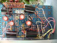
Mine has a separate supply and it does hum a bit more than I would like.
I have included a picture of the underside of my board which shows the ground buss. Call it a picture of what not to do. I connected the negative PS terminal to the centre of the u shaped buss with the intention of using one leg for each channel. When I wired it up it did not turn out that way. It seems to late to change it now. Anyone think this is where I went wrong?
Rolf.
Attachments
rman said:Mine has a separate supply and it does hum a bit more than I would like.
I have included a picture of the underside of my board which shows the ground buss.
I think your problem is what they call "lead dress". Basically neatness does count.
Some techniques are to tightly twist the heater wires and route them very close to the chassis metal and well away from signal leads. Cross at close to 90 degrees. Minimize wire lenghts by using straight lines. Use sheilded wire when required, I don't see the point of the PCB. Why not use a turret board or something else that is more compact. being compact means less wire.
You could also go with regulated DC heaters.
Here is a random photo that shows some of this
http://www.silvatone.bravepages.com/HO/Graphics/Wiring - Circuit Board.JPG
Notic in the above how the power supply and the input section are on oposite sides. Also see the input jack that is wired with coax directly to the tube's grid pin
Hi Chris.
All very good points. maybe I will try a complete rebuild one day.
I suspected the heater wiring myself at first. Since I used an outboard supply, it was a simple matter to run the heaters with a lantern battery to see if a pure dc would solve it. No difference. So even though it looks a mess that part isn't it. I have also tried using shielded cable on one input to see if it would cure one channel but it did not so I left the other alone. Also added a ground breaker, no dice. Then I upped the raw supply voltage and added RJM'S mosfet "regulator". Now ripple is almost undetectable on my scope. So I guess it does come down to a neat, compact layout and keeping the sensitive low level signals away from the high current parts. Oh well, live and learn. Can't afford to rebuild it now and it sounds quite good despite it's flaws.
fourtytwo
Have you decided on a design yet?
Cheers.
I have decided to do the RJM design.
From my reading this is what i got so far.
all caps would be poly film caps (brand?) I would prefer to order from mouser but they dont carry illionis caps. I will some day replace the coupling and riaa caps with expensive ones but i just want to do it reasonavbly for now.
For resistors i think it looks like every one uses wire wound precision ones. I do have a pile of old carbon risistors given to me by a univac tech. Would these be ok to use.
sockets new, tubes new or used. Wiring solid copper, interconnects good gold plated ones (Brand?)
The powersupply just good 105 degree caps. Random parts stole out of old copiers.
a question, on the build page there is mention of using 2x8uf caps on the B+ input for each stage on the amp end? What exactly is meany by this? What type of caps? electrilital?
Thanks
FortyTwo
Hi fourtytwo.
Life the universe and everything?
I used Solen caps for coupling and the B+ bypass caps. I think these are the ones you mean, they are extra power supply filters. The designer recommended the Solens. Blackgates for cathode bypass. They are expensive and getting hard to find. I think Nichon? are popular for this. For the riaa caps I couldn't get high precision ones so I bought lots of cheap ones and a capacitance meter. 1% metal film resistors here. I used multi turn pots but they maybe causing some white noise. Metal oxide resistors for the plates and cathodes. Carbon types are said to be noisy when high value or at high voltage. For tubes I used new Electro Harmonix 6922's. I also tried some JAN Sylvania 6DJ8's. These sounded fine as well but are much more microphonic. Interconects, I guess just keep them short.
Cheers.
8audio sale preamp parts etc
http://stores.shop.ebay.com/8Audio_...Z1QQ_sidZ416308020QQ_trksidZp4634Q2ec0Q2em322
--------------------
http://stores.shop.ebay.com/8Audio_...Z1QQ_sidZ416308020QQ_trksidZp4634Q2ec0Q2em322
--------------------
- Status
- Not open for further replies.
- Home
- Amplifiers
- Tubes / Valves
- Tube Phono Preamp PCB Ebay? are these any good