Bunch of cathodyne questions --
First, what am I looking for in an optimal cathodyne tube? High mu? High Gm? Certain current? Or is it simply a matter of working within the power supply constraints and using a linear tube.
Second, if I am AC coupling the grid and using cathode bias, should the cathode bias + the cathode load = the plate load, or is the bias resistor ignored, or need it be bypassed? Is an LED a good option for bias?
Third, assuming I am using a resistor for biasing, is it necessary to take the output from the base of the bias resistor, or does straight from the cathode make more sense.
Finally, how much bias is necessary? Is this more an issue of sufficient current, or is a certain bias necessary to avoid overdriving.
Biasing is no different than any other use. Typically, the grid resistor is returned to the bottom of the bias resistor, then the signal is yaken from that junction (and the opposite polarity, of course, from the plate). An LED works very well in the application, connected between cathode and the return of the grid leak. The cathode bias resistor can, alternately, be bypassed. Because the signal is taken from there, the plate resistor and the resistor from the bias resistor/grid leak resistor junction to ground are matched.
If the load is guaranteed not to leave class A (i.e., the loads remain symmetric under all conditions), the tube parameters are all pretty second order- high gm will help keep the source impedance low. If the load might change under some signal conditions (e.g., an AB output stage as a load), low mu is an advantage, since that will reduce drive asymmetry.
If the load is guaranteed not to leave class A (i.e., the loads remain symmetric under all conditions), the tube parameters are all pretty second order- high gm will help keep the source impedance low. If the load might change under some signal conditions (e.g., an AB output stage as a load), low mu is an advantage, since that will reduce drive asymmetry.
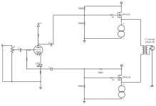
I prefer direct coupling: less of phase shifts on lows == better stability with feedback. If the tube before splitter wants higher plate voltage I use a voltage divider.
Like here:
http://wavebourn.com/forum/download.php?id=119&f=7
Like here:
http://wavebourn.com/forum/download.php?id=119&f=7
dsavitsk said:Bunch of cathodyne questions --
First, what am I looking for in an optimal cathodyne tube? High mu? High Gm? Certain current? Or is it simply a matter of working within the power supply constraints and using a linear tube.
Well, high mu will produce the greatest feedback factor, but even lowish-mu valves will make a very linear cathodyne. It'll probably be the most linear thing in the amp...
Low ra is good if you need lots of voltage swing/headroom, which you probably don't, so high gm is the desirable feature, as usual. But anything makes a good cathodyne!
If the bias resistor is bypassed (or an LED) then Ra should equal Rk. If it is not bypassed then Rk+Rbias should equal Ra. LED biasing is an excellent choice.Second, if I am AC coupling the grid and using cathode bias, should the cathode bias + the cathode load = the plate load, or is the bias resistor ignored, or need it be bypassed? Is an LED a good option for bias?
If the bias resistor were unbypassed and Ra = Rk then you would want to take it from the junction of Rb and Rk. It wouldn't be very elegant though. If Rb is bypassed or an LED then it doesn't really matter where you take it from.Third, assuming I am using a resistor for biasing, is it necessary to take the output from the base of the bias resistor, or does straight from the cathode make more sense.
As pointed out, it's the same as for any stage. Hotter bias makes for more gain, more current, probably less noise, but also less headroom. Centre bias makes for maximum headroom.Finally, how much bias is necessary? Is this more an issue of sufficient current, or is a certain bias necessary to avoid overdriving.
FWIW, I maintain that high gm and linearity are important. Fact, phase splitters are frequently found inside GNFB loops. High gm is protection against slew limiting induced by a HF error correction signal.
The 5687, ECC99, etc. are good candidates. Look at Triode Electronics' ST70 replacement driver board. Populated with 2X EF86 and an ECC99, the PCB retains the OEM topology, while using much better active devices.
The 5687, ECC99, etc. are good candidates. Look at Triode Electronics' ST70 replacement driver board. Populated with 2X EF86 and an ECC99, the PCB retains the OEM topology, while using much better active devices.
Check out this article from the Valve Wizard on the cathodyne. His other articles are also outstanding. Clear, concise, with enough math to be practical without being overwhelming.
Wavebourn said:I prefer direct coupling: less of phase shifts on lows == better stability with feedback.
I am trying to keep the PS as simple as possible, and AC coupling helps in that regard.
Eli Duttman said:Fact, phase splitters are frequently found inside GNFB loops.
Well, not here. But, interesting to note for future applications.
flysig said:Check out this article from the Valve Wizard on the cathodyne. His other articles are also outstanding. Clear, concise, with enough math to be practical without being overwhelming.
Neither he, not MJ for that matter, answer the above, which is why I asked
")
Anyhow, thanks for the responses. This is a somewhat unusual application -- it's a buffer for low Z headphones that have been terminated with a balanced connection. Might also make a decent buffered passive preamp.
Attachments
SY said:
...(AB output stage as a load), low mu is an advantage, since that will reduce drive asymmetry.
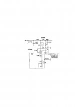
Yes: choose med/low mu types, ECC88 (excellent), ECC82;6SN7 and many RF signal tube types with lowish mu triode sections. I often use a cheap ECF80; the circuit shown gives low thd with symmetrical clipping. Easily 30+30V rms.
Thd 30+30V rms =approx 1%; 3V= 0.1%.
richy
Attachments
- Status
- This old topic is closed. If you want to reopen this topic, contact a moderator using the "Report Post" button.
- Home
- Amplifiers
- Tubes / Valves
- Cathodyne Questions