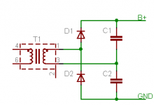
I like checking what the manufacturers are doing today, especially the Japanese. Well there is this EL84 PP amp and i start looking at the power supply and i don´t understand what this diode is doing there. See picture:
What kind of rectifier is this? Half wave?
What kind of rectifier is this? Half wave?
Attachments
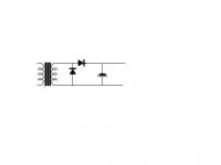
Sawreyrw is correct. As drawn, it's a recipe for disaster. The diode across the secondary will short the transformer out and burn it up. For a voltage doubler, there must be a second capacitor in series with the first (shunting) diode. If you drew this from the existing amp, please recheck it again.
It is difficult to reverse engineer this power supply, it makes no sense!
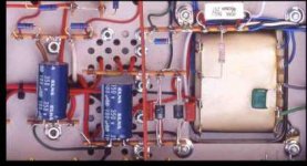
It has to be a half wave voltage doubler, see a better pic.
http://www.audioasylum.com/cgi/t.mpl?f=tubediy&m=152516
It has to be a half wave voltage doubler, see a better pic.
http://www.audioasylum.com/cgi/t.mpl?f=tubediy&m=152516
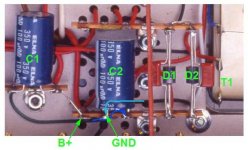
You can see that those diodes go to the same point and one ends in ground. Maybe is a half wave with 2 diodes in series but one is grounded so it cannot be,maybe it is just my mistake following those wires, and all this just out of curiosity....i know the amp sounds great.
Attachments
stalker said:You can see that those diodes go to the same point and one ends in ground. Maybe is a half wave with 2 diodes in series but one is grounded so it cannot be,maybe it is just my mistake following those wires, and all this just out of curiosity....i know the amp sounds great.
It all makes sense if one assumes that the black wires cross under the terminal strip as shown here in blue. That makes it a regular voltage doubler.
I think of a voltage doubler as neither half wave or full wave. It's more like two half wave rectifiers on opposite AC half-cycles, in series.
Cheers,
Michael
Attachments
The schematic posted by stalker is the beginning of a voltage doubler.
Here are some well-designed voltage doubler schematics:
http://www.turneraudio.com.au/powersupplies_files/schem-8585-psu-2ch-05.gif
http://www.bonavolta.ch/hobby/en/audio/211_1.htm
http://www.pmillett.com/images/813_ps_sch.PDF
Here are some well-designed voltage doubler schematics:
http://www.turneraudio.com.au/powersupplies_files/schem-8585-psu-2ch-05.gif
http://www.bonavolta.ch/hobby/en/audio/211_1.htm
http://www.pmillett.com/images/813_ps_sch.PDF
Michael Koster said:
It all makes sense if one assumes that the black wires cross under the terminal strip as shown here in blue. That makes it a regular voltage doubler.
I think of a voltage doubler as neither half wave or full wave. It's more like two half wave rectifiers on opposite AC half-cycles, in series.
Cheers,
Michael
That's the classic definition for a full wave doubler! Which is what the circuit shown in the previous post happens to be...
Thank you . This forum is great . By the way i have found a similar power supply in el Cheapo.
http://homepage.mac.com/planet10/forum/elCheapo-23jun06-map.gif
But this Japanese amp is no cheapo at all.")
It makes me wonder, probably in PP amps the power supply it is not that critical.
http://homepage.mac.com/planet10/forum/elCheapo-23jun06-map.gif
But this Japanese amp is no cheapo at all.
It makes me wonder, probably in PP amps the power supply it is not that critical.
Playing around with various topologies in PSUD2, I have come to the conclusion that, apart from the miserable power factor, voltage doublers are not inherently all that bad. One can tune the DCR in the rectifier loop to balance peak current vs. regulation. Adding an LC stage to a doubler can improve the transient response and reduce ripple to millivolts.
Michael Koster said:Playing around with various topologies in PSUD2, I have come to the conclusion that, apart from the miserable power factor, voltage doublers are not inherently all that bad. One can tune the DCR in the rectifier loop to balance peak current vs. regulation. Adding an LC stage to a doubler can improve the transient response and reduce ripple to millivolts.
For the same amount of copper in the secondary (half the voltage, twice the current), the doubler performs exactly the same as the full wave bridge, with the same "miserable power factor" (same primary current waveform). The only disadvantage I see is higher ripple current in the input caps, and of course you must use two input caps, where you might use one with the full-wave, at least below 450V. Either one beats the full-wave center-tap for current rating and / or regulation.
- Status
- This old topic is closed. If you want to reopen this topic, contact a moderator using the "Report Post" button.
- Home
- Amplifiers
- Tubes / Valves
- Does this power supply make any sense to you?