Hello to all,
i’am a new entry to the Forum. My name is Emanuele, i have 26 years and i write from Vicenza (Italy).
Are hi fi enthusiast and I like to design acoustic loudspeakers: I am passionate about hi fi and i like to design acoustic loudspeakers: But I know little electronics to judge the quality of amplifier projects!
My old friend, the engineer Diego Barone has done for me (well a few years ago) all the circuitry for the amplifier VALVOLOZZO modified version.
I WANT TO ADD PICTURES OF CIRCUIT AND A PDF WITH MEASURES BUT NOT UNDERSTAND HOW TO MAKE ...... HELP ME PLEASE!
Has already been opened in the past treadh on this amplifier has been critical of the circuit and the type of output transformers.
My output transformer use a toroidal, a capacitor mkp Sonus Faber 72 microFarad and hammond inductance.
Listen to me seemed good, even in low range, perhaps with a little high 'polished.
My system is:
* Technics direct drive turntable with hand made marble plinth, toneaem Moerch DP 6 cartridge mc Fidelity Research Fr 1 mk III-F retipped by Tolai Roberto with Gyger S
* preamp NAD 1300 with Burson Audio op amp
* CD player NAD 5000 + Audio Alchemy DAC
* speakers Sonus Faber Concertino
I am going to make DIY speakers tower with a wideband 13 cm , woofer eminence delta 12 lf in bass reflex + supertweeter Fostex FT 17 H (94 dB/1w/1m)
I would use (if it is a good choice) the amplifier VALVOLOZZO: I just realize the cabinet.
My question is: how can I improve the circuit in my possession?
This project is considered really good or bad? with your help I will understand if VALVOLOZZO set aside to buy a T-amp kit (hypex
I apologize for my bad English ... expect many answers!
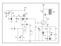
The input stage seems to have a slightly unusual CCS on the top in that it seems to be operating as a constant voltage element - and replacing that with something better might improve the top end clarity and extension (mosfets have high input capacitance ).
Other than that it looks like a well thought out and designed amp. Toroidals in Parafeed amps will far outperform any conventional EI amp. The only thing that can happen is they can ring out at about 50khz. Scoping it up with a signal generator would show any of that up.
The only reason to criticize this circuit is ignorance and prejudice.
Shoog
Ciao Emanuele,
What are the tube types in your amp?
The CVS on top of the input tube has just been discussed and found interesting as it mimics a anode choke at the same time as it has a fixed voltage. It will probably not compromise your top end. Though I wonder about the 1u cap, resistor and potentiometer from anode to ground, some kind of hum reduction?
revintage said:Ciao Emanuele,
What are the tube types in your amp?
The CVS on top of the input tube has just been discussed and found interesting as it mimics a anode choke at the same time as it has a fixed voltage. It will probably not compromise your top end. Though I wonder about the 1u cap, resistor and potentiometer from anode to ground, some kind of hum reduction?
The cap, resistor and potentiometer look like an attempt to improve the low frequency response.
Looking at the circuit, the input / driver looks like its a mu-follower with the required FET bias circuit. See "Valve Amplifiers" P 115 to P 120 by Morgan Jones. (Highly recommended book )
Without knowing the tubes (valves) involved, its impossible to comment further on circuit values.
I agree this is a good design. The design choices all point to someone who understands what he is trying to accomplish.
To me, if you like the sound, leave it alone.
Doug
Without knowing the tubes (valves) involved, its impossible to comment further on circuit values.
I agree this is a good design. The design choices all point to someone who understands what he is trying to accomplish.
To me, if you like the sound, leave it alone.
Doug
Hi Emanuele,
Congratulations on getting this far along!
The circuit topology has no problem I can see, and I do like the
MOSFET driver arrangement: Constant Voltage Mu-Follower.
Having built this driver circuit and tested it, I agree w/Lars that there is
no HF extension problem with the MOSFET. It's gate capacitance is
bootstrapped by the 1K resistor, i.e. when the MOSFET conduction
increases, it's own source terminal helps to drive it's gate. So the
extra capacitance seen by the driver tube is only a small fraction of
the Cgs. I still think it might be slightly improved by using a cascode
instead of a single MOSFET here but I haven't tried it yet.
I also like the cathode regulator circuit in the output. It looks like the
220K/1W feeding the 5.1V zener may be a way to compensate in the
cathode voltage for line voltage changes? I have done something
similar but without the B+ compensation. This provides the stiffness
of fixed bias using a cathode circuit.
What happens when you turn the 22K potentiometer on the driver
anode? That will definitely impact the HF response. Maybe try without
the anode shunt circuit. It looks more appropriate for a pentode, but
maybe you're using a very high Rp driver...
Cheers,
Michael
PS The circuit could easily be adapted for DC drive by increasing the
cathode voltage on the output tube and providing an adjustable
driver anode voltage control for bias setting in place if the 200V zener.
The B+ would need to increase as well. If you match the driver
anode voltage to the output grid... I'm not recommending you do this,
just pointing out the possibility... It would enable a little (or a lot)
of class A2 operation...
- Status
- This old topic is closed. If you want to reopen this topic, contact a moderator using the "Report Post" button.
- Home
- Amplifiers
- Tubes / Valves
- VALVOLOZZO triode amp with toroids output trafo...help me