Hi,
I have some questions to the guys here") !
!
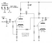
I wish to build a new Tube Pre and was looking at various options and designs, I have almost shortlisted the circuit below and need some opinions on that !! Also if someone has a better circuit (either hybrid or otherwise) please post it here so that I can try to use it !!
Also I have some doubts,Although it seems like a foolish one's but I still have them none the less and want to clear it !!
1) The Current ratings on the tube is not much,but is 50MA sufficient for stereo circuit ?
2) The Heater Current is 300MA according to the datasheet,will it constantly draw that much ? will a 500MA rated trafo work for both the channels (Stereo ) ??
3) I plan to use a Silver plated PCB as opposed to a P2P wiring,So although die hard fans will say no I want to just get a opinion as how bad this can be ??
This is all I can think of as of now !!
Please do share your thoughts and idea's and help me out !
!
Regards.
I have some questions to the guys here
!I wish to build a new Tube Pre and was looking at various options and designs, I have almost shortlisted the circuit below and need some opinions on that !! Also if someone has a better circuit (either hybrid or otherwise) please post it here so that I can try to use it !!
Also I have some doubts,Although it seems like a foolish one's but I still have them none the less and want to clear it !!
1) The Current ratings on the tube is not much,but is 50MA sufficient for stereo circuit ?
2) The Heater Current is 300MA according to the datasheet,will it constantly draw that much ? will a 500MA rated trafo work for both the channels (Stereo ) ??
3) I plan to use a Silver plated PCB as opposed to a P2P wiring,So although die hard fans will say no I want to just get a opinion as how bad this can be ??
This is all I can think of as of now
!!Please do share your thoughts and idea's and help me out
! Regards.
highs will fall off pretty fast with much cable, such a high impedance output. You won't be able to drive anything SS with it, either.
nor do i see the need for feedback.. or why the first tube is run so cold...
as for heater, yes it's constant, so 600mA would be pushing it.
nor do i see the need for feedback.. or why the first tube is run so cold...
as for heater, yes it's constant, so 600mA would be pushing it.
Hi,
Many thanks for the reply !!
I have few doubts and hope you don't mind answering them !
What does that mean ?? are you referring to P2P wiring ?
Ok so how can it be changed to suit the needs ?
Again please would you be kind enough to tell me how to change it to a proper one !!
How will it pushing ?? what I mean is for 2 channels is 500MA ( taking 250MA per tube and per channel ) ? or will a 650MA be sufficient (taking 325MA per Tube/Channel with 25MA as reserve or taking deficiency of the overall PSU in mind ) ?
Sorry if I sound silly,I have many years of experience in SS but this is not something I tried before ! so this is uncharted waters for me !!
Finally if you as said before have a better circuit then I'd be the most happiest person to try it !!
Regards.
Many thanks for the reply !!
I have few doubts and hope you don't mind answering them !
highs will fall off pretty fast with much cable,
What does that mean ?? are you referring to P2P wiring ?
such a high impedance output. You won't be able to drive anything SS with it, either.
Ok so how can it be changed to suit the needs ?
nor do i see the need for feedback.. or why the first tube is run so cold...
Again please would you be kind enough to tell me how to change it to a proper one !!
as for heater, yes it's constant, so 600mA would be pushing it.
How will it pushing ?? what I mean is for 2 channels is 500MA ( taking 250MA per tube and per channel ) ? or will a 650MA be sufficient (taking 325MA per Tube/Channel with 25MA as reserve or taking deficiency of the overall PSU in mind ) ?
Sorry if I sound silly,I have many years of experience in SS but this is not something I tried before ! so this is uncharted waters for me !!
Finally if you as said before have a better circuit then I'd be the most happiest person to try it !!
Regards.
Hi,
Ok fine here we go !!
1)Its supposed to drive a SS Power Amp ( Nmos and its varites By Quasi,but not limited to it )
2) Precision and Accuracy in Sound, Audiophile ??
3) Normal Gain that one would expect !
4) Distortion and Noise,well whats good here will leave to you guys !!
On more general note, Am sucker for details (will dig any depth to find in the music) and mostly like a Neutral sound (with a small exception of tube colouring ) !
Hope this is enough for some replies now ! else please do ask ! Again I mention here that Am not well versed with Tubes as Am with SS ! so any deficiency in answering the question you guys throw at me should be excusable !!
!!
Regards.
Start by defining what you want the preamp to do. Hifi or MI? Sources? Loads? Desired gain? Distortion and noise target? Then it will be much easier to select and critique a design.
Ok fine here we go !!
1)Its supposed to drive a SS Power Amp ( Nmos and its varites By Quasi,but not limited to it )
2) Precision and Accuracy in Sound, Audiophile ??
3) Normal Gain that one would expect !
4) Distortion and Noise,well whats good here will leave to you guys !!
On more general note, Am sucker for details (will dig any depth to find in the music) and mostly like a Neutral sound (with a small exception of tube colouring ) !
Hope this is enough for some replies now ! else please do ask ! Again I mention here that Am not well versed with Tubes as Am with SS ! so any deficiency in answering the question you guys throw at me should be excusable
!! Regards.
Read VALVE AMPLIFIERS by Morgan Jones
If this is a line amplifier, ie post volume control as drawn, it will have too much gain with a 12ax7 up front. The output is not buffered so you can't drive a solid state amplifer with such a high output impedance right off the plate of the second tube. Most solid state amplifiers if it's BJT (bipolar junction transistor) have an input impedance of around 5K ohm. If the power amp has a jfet input stage then the input impedance is more infinite (=1M ohm). But you still won't be able to drive a cable longer than a few inches with this set up. The cable capacitance will roll off the frequency response. You want a low output impedance (=150 ohm) of a preamp feeding a high or infinite input impedance (at least 20 times higher) in the power amp. Look at Jones book especially the mu follower and the Beta follower. A mu follower has two outputs of different impedances. And choose a lower mu tube like a 6SN7GTB or a 6J5GT. GRH
If this is a line amplifier, ie post volume control as drawn, it will have too much gain with a 12ax7 up front. The output is not buffered so you can't drive a solid state amplifer with such a high output impedance right off the plate of the second tube. Most solid state amplifiers if it's BJT (bipolar junction transistor) have an input impedance of around 5K ohm. If the power amp has a jfet input stage then the input impedance is more infinite (=1M ohm). But you still won't be able to drive a cable longer than a few inches with this set up. The cable capacitance will roll off the frequency response. You want a low output impedance (=150 ohm) of a preamp feeding a high or infinite input impedance (at least 20 times higher) in the power amp. Look at Jones book especially the mu follower and the Beta follower. A mu follower has two outputs of different impedances. And choose a lower mu tube like a 6SN7GTB or a 6J5GT. GRH
SoundsGreat said:Hi,
I have some questions to the guys here
I wish to build a new Tube Pre and was looking at various options and designs, I have almost shortlisted the circuit below and need some opinions on that !! Also if someone has a better circuit (either hybrid or otherwise) please post it here so that I can try to use it !!
** The schematic you posted has high impedance output stage. You should go with a cathode follower type output. It's only a partial schematic, likely intended to be replicated for each input and then going to a level control and then finally an output drive stage. You need the complete schematic, including power the HT power supply.
** Yes the heater runs all the time and does draw full current. It works just like a light bulb. To power to 300ma heaters You need at least 600ma but then you want a small margin so I'd say But you may need more tubes depending on what you need to do in terms of inputs and outputs
** A PCB can be better than point to point wire, could be worse. It all depends of the skill of the engineer would worked out the laayout and design of each. The good thing about PCB is that if you have a good design you can mass produce it and all units will be the same. Either method can be very good. However.... For one off audio work turrent boards workl well because they make the ciruit very easy to modify. And you WILL need to tweek and modify it. So I'd suggest a third option, turrets for a custom design. And yes you WIL be tweeking this. Th "AX" tube may have more gain than you want. For example I'm using your schematic (more or less) in a guitar amp I'm building where I want the preamp driven to high levels of distortion. You may not want so much gain and my go with a AU, AT or AY tube. But it's easy to swap this stuff around
Soundsgreat.
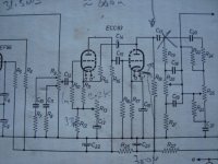
That circuit you shown with -anode feedback to first stage cathode- is the decoy. IT DOES HAS LOWish O/P impedance 660 ohms and excellent running into tone controls.
Chris A; check ?: From my maths it has around 35dB NFB (100K res) although I would prefer a 10uF cap also in series. As it stands with considerable NFB, the response hits 100KHz with ease and thd is also very low,. the noise should be around -70dB down. You can replace the cathode resistor with a CCS red led; (as I do) Morgan Jones technique.
A stepped gain control can be made by adding a cap and resistor from 1st stage junction 15K#1M to ground. Many possibilities with this circuit and is good sounding.
richy
Hi,
Richy Sir, you just made my day !! I was very hesitant to reply thinking how to,coz as said before Am not expert in Tube ! so thought what they might think if I say that this is supposed to be a good circuit !! from whatever little I've understood so far this is supposed to be a very good circuit !
So I ask you,can you please guide me in making it a standalone pre without tone controls ??
As with Chris and others thanks a lot guys really appreciate the help !
Chris I got it ! I've ordered for 650MA winding for the heaters and 100MA for the Plate !! again this is one trafo for stereo !!
Anything else ?? please do let me know !!
Regards.
That circuit you shown with -anode feedback to first stage cathode- is the decoy. IT DOES HAS LOWish O/P impedance 660 ohms and excellent running into tone controls.
Richy Sir, you just made my day
!! I was very hesitant to reply thinking how to,coz as said before Am not expert in Tube ! so thought what they might think if I say that this is supposed to be a good circuit !! from whatever little I've understood so far this is supposed to be a very good circuit !So I ask you,can you please guide me in making it a standalone pre without tone controls ??
As with Chris and others thanks a lot guys really appreciate the help
! Chris I got it ! I've ordered for 650MA winding for the heaters and 100MA for the Plate !! again this is one trafo for stereo !!
Anything else ?? please do let me know !!
Regards.
Morgan Jones valve amps 3rd ed p.499 has a sim setup. Similiar follower circuits can accept a good voltage headroom: The limiting factor being the drive into 2nd stage grid. I use a 6BR7 lo noise pentode (as pentode) and EF184 (strapped as triode) for excellent bandwidth.
richy
richy
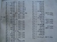
Attachments
Hi,
Thanks a tonne for the advice and help !! really really appreciate !!
!!
Could you please explain how it is done ??
Rest will surely look into this and see how things go !
Regards.
Thanks a tonne for the advice and help !! really really appreciate
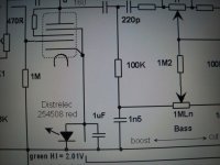
!!You can replace the cathode resistor with a CCS red led; (as I do) Morgan Jones technique.
Could you please explain how it is done ??
Rest will surely look into this and see how things go !
Regards.
I choose a 2nd stage tube with normal cathode-bias volts around 1.6-2V; the red led has the lowest dynamic resistance. Check the tube characteristic curves for the tube one is using.
On the same theme; if you can CCsource and CCsink with disrete trannies you will have a near optimum operating conditions for the tube with excellent performance. Inspect the graphical Vg-cath curves first. Some tubes operate with quite low cathode volts, lower than LED voltage range. However there are ways around this problem.
I decouple the led with a Lo esr film cap; as I often use one red led to run two tubes; the HF performance of led's always slightly degrades with rising frequency.
Buy Morgans Jones books !That's serious.
richy
Attachments
Hi,
Richy thanks a lot ! will look into this and see how can I implement this !
One more question, Am going to order the trafo's tomorrow !! so one final time let me ask you guys to give me go ahead for the below spec trafo !!
Primary : 230V
Secondary 1: 240V/100MA
Secondary 2 : 9V / 650MA
This will be one trafo for a stereo Pre ! So please correct me if Am wrong !!
Regards.
...I choose a 2nd stage tube with normal cathode-bias volts around 1.6-2V; the red led has the lowest dynamic resistance. Check the tube characteristic curves for the tube one is using.....
Seems to me that you are really using the LED as a kind of voltage regulator rather then as a resister. With a resistor voltage is proportional to current but diodes, if they are conducting at all, have a fixed voltage drop. Or maybe this does not apply to LEDS? Are LEDs best modeled as a diode and resistor in series?
If LEDS work what about Zenier diodes?
It occurs to me that you might enjoy reading about the aikido preamp. A google search will turn up plenty of hits and this article is good: http://www.tubecad.com/2004/blog0011.htm
If you like it, PCBs are available for much less than you could make one.
CD
If you like it, PCBs are available for much less than you could make one.
CD
- Status
- This old topic is closed. If you want to reopen this topic, contact a moderator using the "Report Post" button.
- Home
- Amplifiers
- Tubes / Valves
- Another Tube pre query !