Hi all,
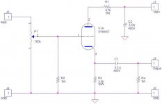
Walking along the lines of a 6AS7 headphone buffer, I butchered the input section of a 6922 and left the 6AS7 alone and ended up with the circuit below. Will it work?
Why do I want to do that? Well they look sexy and are typically so much cheaper that your typical little 9 pin tubes for sure.
cheers
Attachments
Will said:Hi all,
Walking along the lines of a 6AS7 headphone buffer, I butchered the input section of a 6922 and left the 6AS7 alone and ended up with the circuit below. Will it work?
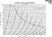
No. Take a look at the plate characteristics. With a DC loadline of 14.7K and 150Vdc, you're operating almost in cutoff. Depending on the impedance of those headphones, you'll probably not get very much output swing either.
If you're gonna go that route, and don't need very much voltage gain, you're better off using both halves of the 6AS7 and making an SRPP stage.
Attachments
Sorry I was not clear enough. I wanted to use that schematic as a preamp buffer to drive my power amplifier with 100K input impedance (not a headphone). I'd sure like to use each half of the tube per channel saving up some cost (as I'll be approaching a 6 channel preamp buffer). Perhaps bumping up to 300V supply will suffice?
cheers.
cheers.
Will said:Sorry I was not clear enough. I wanted to use that schematic as a preamp buffer to drive my power amplifier with 100K input impedance (not a headphone). I'd sure like to use each half of the tube per channel saving up some cost (as I'll be approaching a 6 channel preamp buffer). Perhaps bumping up to 300V supply will suffice?
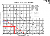
You can definitely do that, but these are still large signal VTs, even if you're using them for small signal purposes. If you want to burn up that much power, it can be done.
Note: Since this requires such a high Vgk, you will need to increase the Vpp to 180Vdc to compensate (unless you go fixed bias).
Attachments
I suggest you make it a preamp gainstage. Will probably sound better than a CF and gain will be very low at 6dB. When you go CF, gain will be -3dB.
You can get away with ca 100V/50mA(best linearity) over the tube and a simple DN2540 CCS on top. Ug will be -40V so a B+ of 180V(140V for CF)should be sufficient. Be aware the cathode resistor(820ohm) will dissipate ca 2W. Zout will still be low at 300ohm. Zout for the CF is about half at ca 150ohm.
Asymmetric clipping will occur in the ballpark of 25Vrms out.
An externally hosted image should be here but it was not working when we last tested it.
revintage said:I suggest you make it a preamp gainstage. Will probably sound better than a CF and gain will be very low at 6dB. When you go CF, gain will be -3dB.
You can get away with ca 100V/50mA(best linearity) over the tube and a simple DN2540 CCS on top. Ug will be -40V so a B+ of 180V(140V for CF)should be sufficient. Be aware the cathode resistor(820ohm) will dissipate ca 2W. Zout will still be low at 300ohm. Zout for the CF is about half at ca 150ohm.
Asymmetric clipping will occur in the ballpark of 25Vrms out.
An externally hosted image should be here but it was not working when we last tested it.
I'd sure prefer the low gain preamp of just 6db rather than a -3db buffer. To be honest I'd also like to salvage as many parts I have as possible and I don't mind sacrificing some amount of linearity bearing in mind that with a 6 channel preamp (into a 3 way fully active system) each 6AS7 channel is only loaded with a certain frequency bandwith hence IMD should not be that big a problem I'd assume.
I have several small 120V AC trans (4 infact) - so these will generate 120*1.4 = 168VDC
If I want to use a simple cathode resistor, to drop 168V to 100V (drop 68V) over 50mA, that would compute to R=68V/0.05=1360ohms
Can I use that value to replace the Dmosfet? Might be daft for simplicity sake, just curious if it can be simplified.
cheers.
- Status
- This old topic is closed. If you want to reopen this topic, contact a moderator using the "Report Post" button.