This kind of issue has crept into the DIYaudio tubes/valves lately, sometimes as an unforeseen event for folk building loop-feedback amplifiers and sometimes from folk working to duplicate historic designs, or both. Understanding the fundamentals of amplifier stability is actually very easy, but it's not easily available to the tubes/valves world. Folk who'd like to understand the easily graspable basics that underlay feedback amplifier design should take the time to study opamps, and the related description of Bode curves. It starts with a description of amplifiers stripped of particulars and details, then adds models of real-world errors to make a non-ideal (real-world) model.
When I read posts here recently I see very bright folk who haven't yet done the opamp 101 work, and want to skip immediately to conclusions, and I'm strongly opposed on principal to short-cutting this learning step. Did too much myself more than half a century ago, so am an honest witness. DIYaudio tubes/valves is a great source, but (necessarily) incomplete. Lore is useful, and very often all that's available/true/believable/interesting/contemporary, but in this case, a fundamental grasp of feedback theory is worth the effort, and too much of Interweb lore is just flat wrong. Only believe what you can prove to yourself; anything else is religion.
All good fortune,
Chris
Last edited:
That's often the case. Dead bug construction works better,but PCBs are best for mass production.In college, I did a project on amp design that turned into a project about stray capacitance. I designed a nice little BJT amplifier and constructed it as a “ball of parts” and it worked great. When I created a PCB for the design and stuffed all the parts, it oscillated like hell.. thus the change in project focus. I was able to get it all stable. But had to do it by adding intentional capacitance and throw away bandwidth..
Dead bugs tend easely to grow out of proportion and strapped with all kind of wires they develope an urge to fall of the workbench. A reflex make you catch em and after killing lots of sand and occasionally also getting the electroshock treatment you would thinck one would have learned something, but no, not me. Happend to me more often than i would like to remember. But the worst was when catching a 100W Weller flying through the air after stumbling over the cord. Hurted like hell and took a really long time to heal.Dead bug construction works better
Sorry, the dead bug made me stray...
Last edited:
Can oscillation increase microphony?
I'm working on an amp I built when I was young and stupid, and I was shocked how microphonic the ECC99 gain stage was. Poking with a probe was clearly audible through the speakers.
(I didn't use gridstoppers facepalm, the operating point is way off also)
I'm working on an amp I built when I was young and stupid, and I was shocked how microphonic the ECC99 gain stage was. Poking with a probe was clearly audible through the speakers.
(I didn't use gridstoppers facepalm, the operating point is way off also)
Such a high value means something is wrong that should be solved without such a resistor.grid stopper resistor from 10k to 180k to solve an awfull oscilation in the pentode.
Post the schematic, with photos of the grid and anode ciruit wiring, and (if possible) the frequency of oscillation.
G2 stopper or G1 stopper? With or without global feedback?
I had too big a “stopper” on an LTP phase splitter, and had about 4 volts of damped ringing on my square waves closed loop. That pole was undesirable.
Then I ended up with some weird RF effects (invisible on my scope) working on the preamp. I ended up needing a cathode stopper on a small-signal LTP which used a current source. Not a “current” source at RF - but a capacitor and a negative resistance.
Global feedback oscillations and local ones require different treatments.
Hello Rod and thank you for the interest.
The oscillation was at 140khz at the pentode part of the ECL84.
I didn't try with something in between 10k and 180k because it solved the problem, but maybe 47k also will do it.
The circuit is in a PCB, so no wiring except for the heater that was wired to the PS.
The oscillation was at 140khz at the pentode part of the ECL84.
I didn't try with something in between 10k and 180k because it solved the problem, but maybe 47k also will do it.
The circuit is in a PCB, so no wiring except for the heater that was wired to the PS.
Attachments
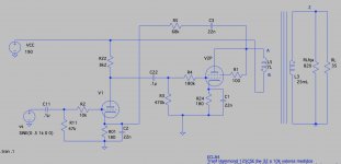
You just made that your dominant pole. With only one stage ahead of your final, this may be practical. Dominant-pole compensation usually puts it it the first stage, and then tries to shove the milller pole in the output stage (or two stages) up as high as possible. Then you would minimize the stopper resistor. 22 nF cathode bypass caps look a little unusual, putting poles in the degeneration at around 40 kHz. At first glance without other calculations I can’t say whether that hurts or helps.
140kHz oscillation means it is not self-oscillation - so a stopper is not the soluton. 140kHz means a loop oscillation, and the problem looks like the feedback is returned to a node of the wrong phase. You can apply feedback to the grid of the same valve, or the anode of the driver (but not the cathode of the driver).
change the G1 resistor to a much lower value, when you have corrected it.
change the G1 resistor to a much lower value, when you have corrected it.
Oh, oh, shame on me, I got confused with the phases.140kHz oscillation means it is not self-oscillation - so a stopper is not the soluton. 140kHz means a loop oscillation, and the problem looks like the feedback is returned to a node of the wrong phase. You can apply feedback to the grid of the same valve, or the anode of the driver (but not the cathode of the driver).
change the G1 resistor to a much lower value, when you have corrected it.

or mabe not, Rk (that are needed to bias the tube) are a negative feedback, that's why they are bypassed by capacitors in order to gain more. The feedback loop is in phase with Rk voltage, increasing the negative feedback.Oh, oh, shame on me, I got confused with the phases.
Your feedback is of the correct polarity to be negative feedback. Phase is a different thing and the two shouldn't be conflated. However, C2 is a mistake, and C3 should be designed out. (To keep the first stage valve properly biased, the resistors will need to be adjusted.)
All good fortune,
Chris
All good fortune,
Chris
I built a 6HJ5 SE and recently changed the triode wiring to UL by using a zener to drop voltage to the screen. I noticed some odd artifacts in the idle noise. Looking at the output on a scope, with the outputs connected to a dummy load, only the right channel was oscillating at 133kHz at about 5 vpp. The source of the oscillation was not from the driver, and I swapped output tubes, oscillation stayed with the right channel. The only thing I can think of is it has something to do with the output transformer. They are Edcor GXSE15-2.5k-6. I did solve the issue with a 1k resistor in series with 3300pF across the UL and plate connections. I would just like to know why this happens?
A. You should eliminate C2 that bypasses R01.
The combination of R5 and C3 does create a gain increase at low and subsonic frequencies (the negative feedback decreases at low and subsonic frequency, falling to zero at DC). The gain at subsonic frequencies is the open loop gain of the amplifier.
So, what can you do?
1. Easy and simple to calculate and just changing a single part . . .
Leave R5 and C3 in the circuit.
But then adjust the value of C11 versus 47k (R11) so that their low frequencies at the input to the input tube grid start rolling off at the same frequency where the R5 C3 combination causes the gain of the amp to rise at low frequencies. One rolls off, and the other rises up at 6dB/octave rates; and the result is a flat frequency response (until the inductance of the output transformer causes its own low frequency rolloff because of the plate & screen impedance of the triode wired output tube driving that primary inductive reactance).
Or
2. You can design DC feedback from R5 (by taking C3 out). But you should use 2 resistors in series from the cathode to ground, and connect R5 to the junction of those 2 series cathode resistors.
That way, you can get the cathode self bias voltage correct, but still have the amount of negative feedback that you want.
That is easier said than calculated, but it can be done.
B.
Hum and Buzz.
1. Even if there is no ripple in the B+, other effects happen.
B+ ground loop from the secondary, rectifiers, and first filter capacitor have to be made short, and not include other filter caps. All the hum and high frequency hash of the large fast rise transient currents to the filter cap need to stay in this local ground loop, and not be passed on to the next filter cap.
2. RCA input jack, input tube grid, and input tube cathode circuit need to be connected to form a local ground loop, and not include other circuitry.
The RCA input jack ground return should be insulated from the chassis, and only be connected to the ground end of the grid leak resistor, and the bottom of the bottom cathode resistor. All that needs to have short wires in the loop. After that local ground loop, connect the bottom of the bottome cathode resistor to the amplifiers central ground and chassis.
3. A 40% UL tap on a 2.5k primary:
So, from the plate tap to the UL tap is 60%
(0.6 x 0.6) x 2500 = 900 Ohms from the UL tap to the plate tap.
Your 3300pF capacitor and 1000 Ohm resistor across the UL tap to the Plate tap at very high frequencies is very heavily loading the output tube plate/screen.
But it does cause some Lead Phase of the plate to the screen (who knows what the leakage inductance from the plate to UL tap is).
The 3300pF cap is 1000 Ohms at 48.2kHz.
If there is high leakage reactance from plate tap to UL tap at 133kHz, that might make the screen and plate relative phase be the cause of the oscillation.
4. Safety First!
Connect the common of the output transformer secondary to the central ground point / chassis.
Prevent the "Surviving Spouse Syndrome".
I thing all the above are true.
Comments please . . . from those who are more knowledgeable.
Have fun re-designing and have fun listening!
Last edited:
6A3sUMMER,
I'm not sure if your response was meant for me. If so, what schematic is it that you are referring to? I can post my 6HJ5 SE schematic, but it may be a day or two before I can complete a drawing. Other than that, I am just curious to know why one transformer with supposedly the same specs would exhibit an issue and the other not. If there are any documents that talk about this type of problem I would appreciate a link or recommendation. I tried a search, but did not come up with anything specifically. Thank you for the information about transformer leakage reactance.
I'm not sure if your response was meant for me. If so, what schematic is it that you are referring to? I can post my 6HJ5 SE schematic, but it may be a day or two before I can complete a drawing. Other than that, I am just curious to know why one transformer with supposedly the same specs would exhibit an issue and the other not. If there are any documents that talk about this type of problem I would appreciate a link or recommendation. I tried a search, but did not come up with anything specifically. Thank you for the information about transformer leakage reactance.
Last edited:
- Home
- Amplifiers
- Tubes / Valves
- Oscillation in tube amps