course it would!
BUt hey - I'm learning here too...
Concepts right though isn't it? And the numbers within the ballpark? And doesn't your scheme rely on all the voltage amp and cathodyne resistors AND the two triodes being on-specification? Good for simpicity of build, bad for tolerance of calculation and design error...
Or am I over-complicating here?
dsavitsk said:Wouldn't it be easier to leave out C1, R4, and R5 (see my post above)?
BUt hey - I'm learning here too...
Concepts right though isn't it? And the numbers within the ballpark? And doesn't your scheme rely on all the voltage amp and cathodyne resistors AND the two triodes being on-specification? Good for simpicity of build, bad for tolerance of calculation and design error...
Or am I over-complicating here?
"I'm amazed that the power supply is putting out 405V if the transformer is only rated for 88mA. Are these monoblocks then?"
These are indeed monoblocs. Sorry I forgot to mention that.
The B+ voltage went up when I installed the SS rectifier , of course, but also went up when I raised the value of the 6V6's cathode resistor to compensate the bias for the higher B+.
As I raised the resistance of the cathode resistor, the B+ went up too. So I raised the resistance of the cathode resistor again, and again the B+ went up. I went through this 3-4 times before I got to the value of 500 ohms on the cathode resistor. Seems as though it works pretty well like this. Sounds MUCH better than the stock bias and 5Y3 rectifier did.
Not that I know anything, but I thought that a 2 stage amp with the first stage being a PP/phase splitter should have less distortion than a 2 or 3 stage that used the first stage or two SE. Is this thinking on the right track, or not in reality ?
Thank you all for your help. I need to purchase some books and read up on this stuff , perhaps I wont have as many questions then.
...............................Blake
Re: course it would!
There's a lot of wiggle room with tubes. Take a look at SY's RLD amp (http://syclotron.com/?page_id=3) The part you are interested in starts on page 3 of the article.
aardvarkash10 said:And doesn't your scheme rely on all the voltage amp and cathodyne resistors AND the two triodes being on-specification? Good for simpicity of build, bad for tolerance of calculation and design error...
There's a lot of wiggle room with tubes. Take a look at SY's RLD amp (http://syclotron.com/?page_id=3) The part you are interested in starts on page 3 of the article.
http://www.aikenamps.com/LongTailPairDesign.htm
Are C1 and C2 absolutely necessary, or can this be run without them ?
Are they needed to block DC , or are they just used for bandwidth/circuit stability ?
........................Blake
Are C1 and C2 absolutely necessary, or can this be run without them ?
Are they needed to block DC , or are they just used for bandwidth/circuit stability ?
........................Blake
Here you go, as promised. Not exactly what I would do, but it's pretty simple.
An externally hosted image should be here but it was not working when we last tested it.
99% sure that you can ignore them. I included them on my schemo just because I had that page open, but I've only actually had input caps once on an amp.Nihilist said:Are C1 and C2 absolutely necessary, or can this be run without them ?
Yup. I ran the output stage through Push-Pull Calculator (a simulation program). Power at full output should be 3.8W, 3.0 of which are in class A, with .6% 3rd harmonic and .04% 5th harmonic. The bias point, for future reference, is -24V, 35mA per tube.
Of course real-world values might be a bit different..
Of course real-world values might be a bit different..
After reading some of the stuff my helpful fellow DIYer's wrote and linked to , I have come to the realisation that the 6SL7 can't drive the Triode tied 6V6's properly . That being said , I wonder about what this gent mentioned :
"...or even...
ditch the phase splitting completely from the driver stage, and leave it to the outputs as per .Simple EL84 from Yeo... This would allow paralleling of the sl7 to provide better drive"
Would THIS allow the 6SL7 to work better than my previous incarnation ?
http://img188.imageshack.us/img188/323/myversion6sl7gt6v6simpl.png
Is there a way to implement a Long Tailed Pair for the 6V6's , or is that reserved for driver circuits ? If it can be done with output circuits, can it be used with the phase inverting format like in the schematic ?
Thanks for all the help guys ! ......................Blake
gentleman? Moi?
thanks for the upgrade in my status Nihilist...
The basic idea is correct, but I cannot comment on the values you have in place. Be aware that you are limited to Class A operation only, so sorenj's values given above won't apply. The best solution is to put a CCS in the tail of the outputs a la Yeo's lazy man's CCS.
My thinking was that having shifted phase-splitting to the outputs, your 'SL7 can concentrate its meagre energy on overcoming the various capacitances it faces. Paralleled (as you have shown it) I would hope it had enough grunt to do this.
Purists will deride the phase splitting at the outputs thing, but it does address the majority of your issues including keeping the recycling to a maximum!
I am about to build my El86 version of this amp. i will use a 6AU6 as the driver and have it driving the output pentode with plate to plate feedback. The second tube will be a simple pentode with regulated screen and earthed grid.
For the output I will have a pair of CCS, one in each cathode (rather than Yoe's single CCS which needs DC balancing) which will allow me to precisely control the standing DC through the output. I will then tie a pair of back to back caps (1000uf each) between the cathodes, with the junction tied to earth via a 1meg resistor, and this will turn the outputs into a DC balanced AC LTP.
That is how I will be doing it.
Shoog
pp amp design, your thoughts please
Blake,
I had a 6SL7 ltp splitter/driver similar to Sorenj's proposal driving a pair of 6V6 s, but the finals were UL instead of triode and were e-linear connected with the screen voltage providing B+ for the 6SL7 s, which is effectively plate to grid feedback for the finals. I couldn't get that ltp version to work well - ground problems, noisy, and wouldn't balance - so I went to a neg. rail a la Poinz, -140v under a 60K tail - which, I think, works very well and drops the parts count. I have the same ltp driving 7591 s, now, and, again, I'm pleased with the results. With 400v B+ you'd have about 250v on the 6SL7 plates, which would be prime.
I plan on building a variant of the SIMPLE EL84 amp, but using the 6SL7GT and 6V6GT's that I have.
If I am going to "parallel" the two internal triodes of the 6SL7GT for use as a SE driver, which is the proper way to do it ?
If I used this as a starting point for bias : http://img7.imageshack.us/i/6sl7gtfromaikenamps.gif/
Would I use A , B , C , or something else ?
http://img259.imageshack.us/img259/2655/whichisproperwaytoparal.png
Thanks again.....................Blake
Nihilist said:
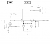
If you're going with that design, I would implement it as shown here (attached). Keep in mind that this particular design will be strictly Class A, and so no benefit of higher output power that you get from Class AB operation.
Is there a way to implement a Long Tailed Pair for the 6V6's , or is that reserved for driver circuits ? If it can be done with output circuits, can it be used with the phase inverting format like in the schematic ?
Give each 6V6 its own tail load, so that these operate separately so far as DC is concerned, so that you may set the Ipq's of each 6V6 to the same value to minimize any DC core magnetization that otherwise might occur. Connecting the cathodes together through the coupling capacitors makes the stage an LTP at AC. You need a 1.0M resistor from the center of the capacitors to ground so that these will polarize properly, as they will need to be some big electrolytics (figure 2200uF at a minimum). These should be good quality, and bypassed with smaller capacitors (~0.1uF -- 0.22uF, polypropylene) for better high frequency performance
So far as paralleling the halves of the 6SL7, simply connect: K1 to K2; G1 to G2; P1 to P2. Don't forget that after doing a loadline, that Ip doubles, and your actual Rp= 0.5Rp (design nominal). The effective r(p) is also cut in half.
Some audiophoolz might complain about this, but t'hellwiddem. Only one way to find out, and that's to try it. If you like how it sounds, great. If not, well, you'll know what not to do the next time. It won't be a complete loss.
Attachments
Miles Prower said:
If you're going with that design, I would implement it as shown here (attached).
* * *
as they will need to be some big electrolytics (figure 2200uF at a minimum).
Neat idea -- how did you arrive at the size of the caps? Seems that if they both go to ground, they can be a lot smaller, so how does this arrangement change that?
My understanding is that they need to be twice the normal calculated size of a bypass cap. this is because they are in series and so their effective value is halved. I have used this scheme in three amps (thanks to Brian Beck for the original idea) using 1000uf caps, all have been very low output impedance designs - and all have had response down to 10hz.
Hope that helps.
Shoog
Hope that helps.
Shoog
Shoog said:My understanding is that they need to be twice the normal calculated size of a bypass cap. this is because they are in series and so their effective value is halved.
Right, I knew that part
") I guess it is that a typical Rk bypass is sized considering, roughly, Rp + rp in parallel with Rk. Rk here is near infinite here, so I am wondering why we can't get away with a single 100u motorrun or something?
I guess it is that a typical Rk bypass is sized considering, roughly, Rp + rp in parallel with Rk. Rk here is near infinite here, so I am wondering why we can't get away with a single 100u motorrun or something? In other words, considering these to be two SE stages, Rk bypass would be considerably smaller, and if each stage just had a cap from the cathode to ground, the signal path would be largely the same with smaller caps. I am likely totally wrong, of course, but I am just trying to understand what's going on.
I have seen one implementation which uses a10uf cap which obviously worked. These were bypassing 6080 cathodes. There was talk of a resonant tank, but I wouldn't use a resonant tank in this position.
I suppose its one of those situations where empirical data is lacking (because no one implements this stage) and so a bit of experimenting is in order. Consider that the electro caps are in back to back series - which by all accounts linearizes their response. My experience is that it sounds better than simple cathode bypassing with the same electros. Better bass and cleaner highs.
Shoog
Alright, I'm sold on the use of a CCS. Their cheap enough and simple enough to implement . I am planning on going with Yeo's LMCCS , I can get the LM317's from Rat Shack .
Will I need to run a heatsink on these ? I plan on using one for each device .
I'm assuming the cathode voltage falls into line due to Ohms Law and the use of a current source ?
In the schemo's listed with the "back to back" electrolytics , do the caps need to be of the "non polarised" variety ?
How critical is the 1meg resistor that polarises the caps ? Is it important enough that I would need to use a quality resistor, or can I just use a carbon that I already have ?
Thanks a ton guys ! ! !
....................................Blake
Nihilist said:In the schemo's listed with the "back to back" electrolytics , do the caps need to be of the "non polarised" variety ?
You provide a DC reference to avoid that.
How critical is the 1meg resistor that polarises the caps ? Is it important enough that I would need to use a quality resistor, or can I just use a carbon that I already have ?
All that resistor does is provide a DC reference. There won't be any significant audio current through it, so it doesn't need to be one of those audio "Magic" resistors.
- Status
- This old topic is closed. If you want to reopen this topic, contact a moderator using the "Report Post" button.
- Home
- Amplifiers
- Tubes / Valves
- PP amp design , your thoughts please.