I have been running the output section of this design for about 2 years now driven by a 6AN8, so no problems there .
I plan on running a 6SL7GT input section instead of the 6AN8 . My circuit values are based off of a 6SL7GT spec sheet .
Output tubes are triode tied 6P6S (similar to Tetrode 6V6GT ) , and input tube is 6SL7GT.
I have 2 different designs in mind, one with bypassed cathode resistors, one without.
Am I missing anything obvious here ? Anything that is taboo or plain stupid ?
With bypass capacitors :
http://img17.imageshack.us/img17/7360/my6sl7gt6v6ppamp.png
Without :
http://img199.imageshack.us/img199/3485/my6sl7gt6v6ppampwlocalf.png
I understand using the circuit that does NOT have bypass capacitors will have less gain. I understand each gain stage will have a loop of local feedback.
Will this reduce dynamic peaks , or is it simply an overall gain reduction meaning that I will have to turn the volume knob up a little more for the same output ?
Any comments or words of wisdom ?
Thanks...........................Blake
That looks like it's going to distort heavily. There's not a whole lot there to force the two triodes to balance closely.
510K on the anode of a 6SL7 is pretty harsh. I'm not even sure it'll work properly.. if you're going for a Long-Tailed Pair, you want to read this link and re-do some math:
http://www.aikenamps.com/LongTailPairDesign.htm
That's a simple approach that just uses resistors, but if you want to get perfect balance, try an LM334 instead of the 1.2K resistor fed by a small negative supply rectified off of your 6.3V heater winding.
405V (375V a-k) is really harsh for any 6V6. I really wouldn't recommend it, especially not with those Russian tubes.. I've heard they're fragile. What's the primary impedance of your output transformer?
A word to the wise: Trioded 6V6's put out a really disappointing amount of output power, typically around 4-5W in push pull. But hey, you're looking at vanishingly low distortion, so if you have 98dB+ speakers, it might be the thing for you.
Cooking the tubes to squeeze some more wattage out of them isn't really safe.
What does your power supply look like? Could you maybe use some beefier tubes instead of 6V6's?
a grid leak resistor on the input 'sl7
would be nice...
Design - wise, I haven't worked the numbers on the rest of it, but I suspect performance would improve by an order of magnitude if the 'sl7 had a CCS in its tail.
What swing do you need on the output tube to get a full output?
It seems to me (but I am prepared for contradiction) that you have waaaaaay to much resistance in your 'sl7 anode, and/or waaaaay to little in your cathode resistor.
Use the curvesfrom this datasheet rather than the chart and work through the maths - you will more likely get a better result. At worst, it will improve your understanding of whats going on!!! Did for me anyway.
CHeers
"That looks like it's going to distort heavily. There's not a whole lot there to force the two triodes to balance closely."
Which Triodes, the 6SL7GT 's ?
"510K on the anode of a 6SL7 is pretty harsh. I'm not even sure it'll work properly. "
I got that from here :
http://tdsl.duncanamps.com/dcigna/tubes/sheets/ge/6sl7-2h.gif
I know it's simple, that's kinda the point of the design. I am using the Reflektor 6V6's cause that's what I've got. I've been pounding on them at this voltage for about two years and they handle it WAY better than a set of Magnavox 6V6GT's I've got.
My speakers are about 97db or so. It plays pretty loud with my current setup, and I don't think it's even driving the 6V6's to full output .
I am thinking of a KT88 design in the future, but this is for now.
Here's a pic of my current Power Supply :
http://img14.imageshack.us/img14/9816/myrevisedpowersupplyfor.png
Thanks for your time............................Blake
"What swing do you need on the output tube to get a full output?"
Not sure, but I think a set of PP 6V6's need about 25V for max output.
"It seems to me (but I am prepared for contradiction) that you have waaaaaay to much resistance in your 'sl7 anode, and/or waaaaay to little in your cathode resistor.
Use the curves from this datasheet rather than the chart and work through the maths - you will more likely get a better result. At worst, it will improve your understanding of whats going on!!! Did for me anyway."
I used the GE datasheet : http://tdsl.duncanamps.com/dcigna/tubes/sheets/6sl7gt.html
Amazing how different the resistance coupled amp charts are for the same tube !
I would like to stick with the output section (6V6) as is, but if you guys can steer me towards a good basic setup that uses a cathode resistor (rather than a CCS) for the 6SL7GT , I would be thankful.
Thanks..............................Blake
Nihilist said:I have 2 different designs in mind, one with bypassed cathode resistors, one without.
Am I missing anything obvious here ? Anything that is taboo or plain stupid ?
That SUX. If you want a simple design that will actually work right, see This Project. The designer of that has a lot of posts right here. Look for "Poindexter" or "Poinz" with the search feature.
"That SUX. If you want a simple design that will actually work right, see This Project. The designer of that has a lot of posts right here. Look for "Poindexter" or "Poinz" with the search feature."
I guess subtlety isn't one of your strong points.
I am well familiar with Poindexter's Musical Machine. Thanks for pointing to it as a reference, as it has been inspiration for me.
Perhaps instead of telling me it SUX, you could tell me WHY it sux ?
Many people will tell me that my OB speakers suck , too. To each their own. I know of the problems associated with them, and their problems are less irksome to me than other designs.
As far as tube design goes , I am much less knowledgable. My thought was to build a simple design based on the parts at hand. Sorry if it isn't "State of the Art" .
Thanks again.........................Blake
I never answered your question about my OPT. I am running these : http://store.triodestore.com/tf65wscta48o.html
I am running them with the 8 ohm tap connected to 8 ohm nominal FR speakers.
..........................Blake
I am running them with the 8 ohm tap connected to 8 ohm nominal FR speakers.
..........................Blake
Nihilist said:I guess subtlety isn't one of your strong points.
Something came up and I couldn't finish the post.
Perhaps instead of telling me it SUX, you could tell me WHY it sux ?
You can't run a 6SL7 that thin and expect it to drive a final. The 6SL7, being designed to operate with very small plate currents (as little as 100uA) likes loads that are Hi-Z and Lo-C -- and that doesn't describe the grid circuit of power finals. With those huge plate resistors (unless you're running off a 1000V rail) mean a very small current. There won't be enough current sourcing at the grids of the finals to charge up the Cgk + Cmiller + Cstray at the higher frequencies, and you'll have a slew problem. The behaviour on transient over drive is also going to be hideous since the 6SL7s will roll over and die at the first hint of grid current.
Better to run them hotter, and include a negative rail for a larger tail load for the LTP. Better still would be an active tail load. All these problems Poindexter addressed in the design of his front end.
I'd suggest a different VT for the front end, but if you simply must have 6SL7s, them I'd suggest using cathode follower grid drivers (6SN7, 6FQ7, 12BH7, 12AU7 (even that one will work here)) Run 'em off a negative rail and you can use fixed bias on the finals. Also, source followers work nicely for this as well, and both will present the 6SL7s with a much friendlier load than any final. That'll take care of the slew rate problem and greatly help out at the high end.
Those are fine output transformers, you have some potential with this circuit 
Miles: Look, the guy wants to keep it simple and use the parts he has; adding a whole negative supply doesn't seem like what he's asking for.
Nihilist: Just tell us what your power supply looks like and I'll design a simple layout FOR you and post it here (I'm feeling generous). It won't be the best thing in the world but it might as well be compared to what you posted already (no offense). You'll just need a few new resistors, maybe a capacitor or two, and some rewiring.
I need:
Power transformer secondary voltage & current
And the rest of your PSU- what rectifier, etc?
The PSU is actually pretty important for sound quality.
...or even...
ditch the phase splitting completely from the driver stage, and leave it to the outputs as per .Simple EL84 from Yeo... This would allow paralleling of the sl7 to provide better drive
ditch the phase splitting completely from the driver stage, and leave it to the outputs as per .Simple EL84 from Yeo... This would allow paralleling of the sl7 to provide better drive
Here's my current PS : http://img14.imageshack.us/img14/9816/myrevisedpowersupplyfor.png
It is currently powering this :
http://img198.imageshack.us/img198/4136/myampschematic169aarevi.png
If you look in the lower left hand corner of the PS link you can see the Sams "hard numbers" .
Primary is 117VAC @.62A ,
Secondary is 612 VCT @ .082A ,
5V @ 2A
and 6.3V @ 1.2A
I am running these for rectifiers : http://store.triodestore.com/ssr.html
I am willing to try the simple EL84 circuit. I've looked at it a few times.
I'm not stuck on using the 6SL7GT's, but I DO have a matched pair staring at me.
.............................Blake
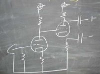
zigzagflux said:Gotta love the old chalkboard")
For all the progress of the digital age, there is nothing like a chalkboard for quickly sketching out ideas -- it was the essential tool for my dissertation.
Nihilist,
Some obervations on your amp design:
1.You cannot bypass the cathodes of the 6SL7, because you're using it as a cathode-coupled (A.K.A. LTP A.K.A. Schmitt) phase splitter. If you bypass the cathodes, where's the signal for the lower triode going to come from?
2, It shouldn't make any difference whether or not you bypass the cathodes of the triode-connected 6V6s if they're well matched, but you can try it to see if it sounds better. It won't affect the gain because the cathodes are strapped together,
3. A plate load of 510k for each 6SL7 is about 4 times what it should be. In any case, it is shunted (at signal frequencies) by a 1M OP stage grid resistor.
4. As said, a 6SL7 should not be used to drive 6V6 in triode mode. It's able to drive the 6V6 in pentode mode, but not triode.
5. The 6SL7 LTP as designed will work very poorly, because there is too low a voltage between cathodes and ground. The simplest way to overcome this problem would be to elevate the cathodes by either adding a bias resistor (as in Aiken's example) or using a potential divider from B+ to the grid of the lower 6SL7 to ground. Either way, you'll need to use an extra cap on the IP grid (of the upper 6SL7). With the cathodes elevated, you will need to use a higher value of common cathode resistor or, far better, a CCS using a BJT cascode, ring of 2, or other SS device(s), for proper balance.
I'm amazed that the power supply is putting out 405V if the transformer is only rated for 88mA. Are these monoblocks then?
I drew up a schem but it's a little late, I can post it tomorrow.
Are you OK with buying a couple chokes to help drop your B+ a little, blacken the sonic background, and stiffen your supply?
I designed for one of these per monoblock. Just bolt 'em in..
http://angela.com/hammondchoke159p.aspx
I drew up a schem but it's a little late, I can post it tomorrow.
Are you OK with buying a couple chokes to help drop your B+ a little, blacken the sonic background, and stiffen your supply?
I designed for one of these per monoblock. Just bolt 'em in..
http://angela.com/hammondchoke159p.aspx
open to comment...
ok, I hope the numbers work... designed to reduce part count to the minimum, stick with the specified major parts without expensive extras, and acheive the output desired.
Issues - will require an elevated or floating heater supply. Easy technically I know, but simpicity rules...
Requires a fixed bias supply - same caveat as above.
Grid stoppers may be a good idea on the output tubes. Dunno. A cheap insurance policy anyway.
Power supply coming...
EDIT!!!! - wahahahahahahahaha... supply voltage ot the voltage amp and splitter should read 250V not 300V. Mea Culpa
Attachments
- Status
- This old topic is closed. If you want to reopen this topic, contact a moderator using the "Report Post" button.
- Home
- Amplifiers
- Tubes / Valves
- PP amp design , your thoughts please.