Yes that is very cool from an engineering perspective, but you completely missed my question! How do these things SOUND???
Okay to be fair I must have been thinking (how do they sound) and should have asked more explicitly")
Right, the amp was very powerful sounding compared to my benchmark 300B push-pull amps that put out about 12 WPC. I was measuring 20W out and using an output transformer rated at 10W, so power bandwidth did suffer some. Even so, there was plenty of bass down to 40 Hz based on playing through JBL 4320s. Treble extension was great, and overall the amp sounded neutral in terms of not adding any noticeable coloration.
I think with properly sized OPTs, it would have great low end punch with the moderately efficient 92db speakers. Also the larger OPTs would probably have lower DCR and improve the speaker damping some.
The exercise did what I wanted, which was to find out that I like the sound of a powerful SET amp.
Cheers,
Michael
PS measurement wise, the second harmonic dominated until about 4-5 watts, then the 3rd harmonic kept equal with the second until clipping. The driver operates into it's low gm region to swing the power grid positive. I learned that some tuning of the source resistor value can reduce the remnant of the "hockey stick" grid current seen by the driver anode in this region, extending the range of the 2nd harmonic dominance.
I'm a hybrid enthusiast. To me the advantage is to use a tube gain with mofset follower that way you get rid of the OPT. But I haven't found an elegant method to avoid large coupling caps on the output.
Anyway I do believe that hybrid amplifiers are the future. And am glad to see another method.
Anyway I do believe that hybrid amplifiers are the future. And am glad to see another method.
Right, the amp was very powerful sounding compared to my benchmark 300B push-pull amps that put out about 12 WPC. I was measuring 20W out and using an output transformer rated at 10W, so power bandwidth did suffer some. Even so, there was plenty of bass down to 40 Hz based on playing through JBL 4320s. Treble extension was great, and overall the amp sounded neutral in terms of not adding any noticeable coloration.
I think with properly sized OPTs, it would have great low end punch with the moderately efficient 92db speakers. Also the larger OPTs would probably have lower DCR and improve the speaker damping some.
The exercise did what I wanted, which was to find out that I like the sound of a powerful SET amp.
Cheers,
Michael
PS measurement wise, the second harmonic dominated until about 4-5 watts, then the 3rd harmonic kept equal with the second until clipping. The driver operates into it's low gm region to swing the power grid positive. I learned that some tuning of the source resistor value can reduce the remnant of the "hockey stick" grid current seen by the driver anode in this region, extending the range of the 2nd harmonic dominance.
Hey Michael,
Thanks for delving further into the amp's characteristics. I have been using a 211 SE amp for the past two months and love its sound. Unfortunately it's not mine, so I will need to be building myself one. I have been hunting around for the output tube of choice and so far 211 is an easy winner over other thoriated tungsten transmitters. It doesn't take too much heat, it's easy to bias and does not require strong A2 right away, sounds wonderful and passes characteristics of previous stage, and should be in current production for the foreseeable future.
However... It's very tempting to go with something a bit more esoteric such as the 4-65. It seems to be a nice Eimac tube that hasn't been noticed as much as the 75tl through 304tl's. What do you think about this tube's availability?
Thanks!
-Michael Woods
I'm a hybrid enthusiast. To me the advantage is to use a tube gain with mofset follower that way you get rid of the OPT. But I haven't found an elegant method to avoid large coupling caps on the output.
Anyway I do believe that hybrid amplifiers are the future. And am glad to see another method.
regal,
I have not tried this and it might be a completely inappropriate idea in this application, but just for kicks... Do you think it's possible to use a capacitance multiplier here?
-MW
regal,
I have not tried this and it might be a completely inappropriate idea in this application, but just for kicks... Do you think it's possible to use a capacitance multiplier here?
-MW
I guess that's another name for a DC balance servo, which drives one end of the output (transformer) with a slowly changing correction signal to match the average DC voltage of the output node. I would integrate the DC offset across the output or OPT primary to derive the correction signal. This acts in effect like a big capacitor.
Hey Michael,
Thanks for delving further into the amp's characteristics. I have been using a 211 SE amp for the past two months and love its sound. Unfortunately it's not mine, so I will need to be building myself one. I have been hunting around for the output tube of choice and so far 211 is an easy winner over other thoriated tungsten transmitters. It doesn't take too much heat, it's easy to bias and does not require strong A2 right away, sounds wonderful and passes characteristics of previous stage, and should be in current production for the foreseeable future.
However... It's very tempting to go with something a bit more esoteric such as the 4-65. It seems to be a nice Eimac tube that hasn't been noticed as much as the 75tl through 304tl's. What do you think about this tube's availability?
Thanks!
-Michael Woods
I like the 4-65A a lot; in triode mode it looks a lot like the 845 wrt. plate resistance, gm, even the plate curves... with a little lower dissipation rating. In practice, the 4-65A *should* be run at about 55 watts to keep the getter healthy, so it's a lot like a lot of 845 amps. Filament is manageable also.
The 4-65A seems to be in fairly good supply but I will stick to NOS from now on. Used ones are 80%+ junk, and even new ones can be about 50/50.
regal,
I have not tried this and it might be a completely inappropriate idea in this application, but just for kicks... Do you think it's possible to use a capacitance multiplier here?
-MW
I guess that's another name for a DC balance servo, which drives one end of the output (transformer) with a slowly changing correction signal to match the average DC voltage of the output node. I would integrate the DC offset across the output or OPT primary to derive the correction signal. This acts in effect like a big capacitor.
Using an 811A
Michael
Was impressed by your circuit in Post 19 and thought that it could be easily adapted to an 811A. Have tried several three tube circuits with 811A in Class A2 and have found the sound to be particularly good. There is a nice operating point of Vpk = 430V, Ip = 95mA and Vpk = +22V into a 5k load. The grid current draw is around 22mA, This is similar to your 35TG valve. The thing I like about the Post 19 circuit is no need for a negative supply. A little unsure about adapting especially the source resistor for the above operating conditions. Would appreciate any comments or help. Thanks in advance.
Ejam
Why MOSFETs? A 6DJ8 or 5687 will drive 50mA peak grid current no problem.
Heck, and if it's still too squishy for 'ya, you could use a pentode-driven "mu" stage with mondo gain, and wrap NFB around the thing to reduce the drive impedance to a couple of ohms. Going from ~2k gain down to 20 or so, you'll drop Zo from maybe 100 ohms to...just a couple?
Speaking of ridiculously low impedances, 2N7000, LEDs, resistors: jokes, all of them. TL431 is adjustable and comes in at an ohm or two, and is priced similar to a 2N7000 or red LED. Rated up to 100mA and 30V, it will handle anything you put it under; output tubes will need an additional pass transistor or voltage divider to accommodate the higher power dissipation, of course. And the voltage is a hell of a lot more stable than some crapMOS (check the tempco of Vgs(th)!).
Of course, a regulated voltage at the cathode of a class A stage is momentously pointless, a resistor is the best solution. Don't bother with anything else, and don't let liars mislead you otherwise!
Tim
Why MOSFETs? A 6DJ8 or 5687 will drive 50mA peak grid current no problem.
Heck, and if it's still too squishy for 'ya, you could use a pentode-driven "mu" stage with mondo gain, and wrap NFB around the thing to reduce the drive impedance to a couple of ohms. Going from ~2k gain down to 20 or so, you'll drop Zo from maybe 100 ohms to...just a couple?
Speaking of ridiculously low impedances, 2N7000, LEDs, resistors: jokes, all of them. TL431 is adjustable and comes in at an ohm or two, and is priced similar to a 2N7000 or red LED. Rated up to 100mA and 30V, it will handle anything you put it under; output tubes will need an additional pass transistor or voltage divider to accommodate the higher power dissipation, of course. And the voltage is a hell of a lot more stable than some crapMOS (check the tempco of Vgs(th)!).
Of course, a regulated voltage at the cathode of a class A stage is momentously pointless, a resistor is the best solution. Don't bother with anything else, and don't let liars mislead you otherwise!
Tim
Yes of course we know mu can be used here and it has been tried. FET source followers actually sound better!
I am still going to try a JFET current-biased in an input tube's cathode. Hadn't thought of the TL431 though! Sometimes cathode bias with a resistor sounds nice, sometimes it doesn't. It's just another flavor.
Why MOSFETs? A 6DJ8 or 5687 will drive 50mA peak grid current no problem.
Heck, and if it's still too squishy for 'ya, you could use a pentode-driven "mu" stage with mondo gain, and wrap NFB around the thing to reduce the drive impedance to a couple of ohms. Going from ~2k gain down to 20 or so, you'll drop Zo from maybe 100 ohms to...just a couple?
Speaking of ridiculously low impedances, 2N7000, LEDs, resistors: jokes, all of them. TL431 is adjustable and comes in at an ohm or two, and is priced similar to a 2N7000 or red LED. Rated up to 100mA and 30V, it will handle anything you put it under; output tubes will need an additional pass transistor or voltage divider to accommodate the higher power dissipation, of course. And the voltage is a hell of a lot more stable than some crapMOS (check the tempco of Vgs(th)!).
Of course, a regulated voltage at the cathode of a class A stage is momentously pointless, a resistor is the best solution. Don't bother with anything else, and don't let liars mislead you otherwise!
Tim
Hey why don't you say how you really feel ;-)
Put in a pentode based op-amp just to avoid a SS part? Would a pentode really perform better? The MOSFET performs quite well in circuit. There's a nice gm-multiplier trick using a TL431 also.
Sure the TL431 is lower impedance, and I will use them where they're really needed. BTW, the dynamic impedance of a 431 is usually less than an ohm. A few ohms of an LED or diode-connected FET is no big deal and it's one component simple.
There's a reason for the regulated cathode. Can you study the circuit and figure out what it is?
Cheers, and thanks for the comments
Michael
Last edited:
Michael
Was impressed by your circuit in Post 19 and thought that it could be easily adapted to an 811A. Have tried several three tube circuits with 811A in Class A2 and have found the sound to be particularly good. There is a nice operating point of Vpk = 430V, Ip = 95mA and Vpk = +22V into a 5k load. The grid current draw is around 22mA, This is similar to your 35TG valve. The thing I like about the Post 19 circuit is no need for a negative supply. A little unsure about adapting especially the source resistor for the above operating conditions. Would appreciate any comments or help. Thanks in advance.
Ejam
It looks like the 811A and the 35t can be used at the same Vpk and Iq for 5K load impedance. The 811 will not use as much grid drive voltage (maybe 60Vp-p vs 100Vp-p for the 35t) but in this plate-grid feedback circuit that won't make any significant difference in the circuit operation. The feedback resistor could be made a little smaller but would work fine as is. The Rfb mainly sets the amp's input sensitivity and driver load line.
Conclusion: the 811 is practically a drop-in with only g1 bias needing a few volts tweaking.
There is no negative supply but it currently uses stacked supplies to keep the grid current loop separate from the cathode. I would like to try with a single supply using a shunt regulator in the cathode ( see attached) as per the "no light district" thread but that will take some experimentation to see how low impedance the cathode shunt needs to be. Grid current in this should not be too spiky since it's in A2 bias.
C1*R7 time constant should be shorter that C2*R5 for good gain stability.
Cheers,
Michael
PS
Hey Tim, here's a TL431 cathode regulator for my driver.
Attachments
Put in a pentode based op-amp just to avoid a SS part? Would a pentode really perform better? The MOSFET performs quite well in circuit. There's a nice gm-multiplier trick using a TL431 also.
Not op-amp (not differential, and the gain is far from infinite). You've got the pentode in there anyway, so why not excorcise all SSin from your amp?
There's a reason for the regulated cathode. Can you study the circuit and figure out what it is?
Nope, nothing the circuit won't do without a resistor (or for that matter, a CCS, to use an extreme example). Bypassed, of course, otherwise AC gain (particularly HF) suffers.
Only thing that cathode controls is its current, which can be anything. Top side voltage reference keeps the operating point stable, which is very handy. (Stable as the dFET anyway, which isn't great...check Vgs(th) vs. temp.)
Tim
Not op-amp (not differential, and the gain is far from infinite). You've got the pentode in there anyway, so why not excorcise all SSin from your amp?
I think we like tube handling voltage amplification and the FET follower doing its thing.
Nope, nothing the circuit won't do without a resistor (or for that matter, a CCS, to use an extreme example). Bypassed, of course, otherwise AC gain (particularly HF) suffers.
Only thing that cathode controls is its current, which can be anything. Top side voltage reference keeps the operating point stable, which is very handy. (Stable as the dFET anyway, which isn't great...check Vgs(th) vs. temp.)
Tim
I think Michael would like you to see the cathode CCS device tracking the constant plate current instead of the other way around?
811A Variation
Michael
Thanks for your thoughts on an 811A variation. Sorry for the delay but being on the opposite side of the world there is always 1/2 day delay in responding. I thought that the 811A was a good candidate as they are readily available and quite rugged, and of course I have a few. As for pentode, I really like the 6688. Will start to tinker on the weekend and report back.
Regards
Anthony
Not op-amp (not differential, and the gain is far from infinite). You've got the pentode in there anyway, so why not excorcise all SSin from your amp?
A second pentode with it's own filament transformer to me would be pointless ;-) But it would work for sure and if it was 1950 I'd be all over it.
Nope, nothing the circuit won't do without a resistor (or for that matter, a CCS, to use an extreme example). Bypassed, of course, otherwise AC gain (particularly HF) suffers.
Only thing that cathode controls is its current, which can be anything. Top side voltage reference keeps the operating point stable, which is very handy. (Stable as the dFET anyway, which isn't great...check Vgs(th) vs. temp.)
Tim
It is to provide a clean stable reference but I see there is some ambiguity about the current loops. And in practice the change is about 0.25V as the dFET warms up. The 2N7000 is < 0.1V the way I use it.
I guess we have to be careful which variant we're talking about but it is the reference for the bias, and RC bias won't work if grid current returns through the cathode resistor. However...
In the actual breadboard I used stacked supplies as in post #1 where the driver idle current + grid current are supplied by the grid supply but only the driver idle current is supplied by the "cathode" supply. The B+ supply is returned to the common cathode point as well. So counting the filament it's four power supplies all common at the cathode. This is the power supply layout for the circuit in post 19 also.
Given this, it's good to have the cathode supply be clean and regulated because it's the reference between input ground and the output tube cathode.
However one could float the bias reference on the cathode instead, letting the pentode Rp decouple the input from the power tube and reduce the regulation requirement on the cathode supply. So maybe it can be simplified after all, but with the stacked supplies there's no idle cathode current in the cathode supply. I need to think about this.
Thanks!
Michael
PS In the post 32 variant with the cathode regulator, both cathode and grid current would return through the regulator.
Last edited:
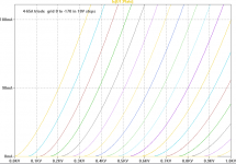
Sorry if this has already been asked, but are there triode curves for the 4-65 that I can use?
Thanks,
-Michael Woods
I got this from Dave Slagle
Michael
Attachments
I got this from Dave Slagle
Michael
Nice! That looks pretty linear to me!
Thanks a bunch.
-MW
- Home
- Amplifiers
- Tubes / Valves
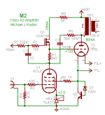
- Class A2 Direct MOSFET Coupled SE