Anyone have any thoughts or preferences about whether to use shielded wire rather than tightly twisted for filaments in a preamp?
I've built several using the twisted method but there always seems to be a slight hum remaining at higher volumes, and I'm considering duplicating the circuit using some silver plated, shielded, teflon insulated cable instead, grounding the shield at each tube (3) and source. Will the extra work be worth it?
Thanks,
Bud
FWIW, the proper manner would be to elevate the heaters as personal preference dictates, connecting the center tap of your transformer to this DC reference voltage. The shield, at the source end, would be tied not to ground, but to this DC reference. A common misconception. Furthermore, I would suggest leaving the shield unterminated at the tube end. If using IDHT, small ceramic caps from each heater pin to earth is a good idea.
I have investigated multiple instrumentation/shielding/grounding books, and done a bit of research at Analog Devices site, and they always recommend the same 'optimal' shielding method as above. Granted, most of these applications were regarding instrumentation amplifiers sensing mV or uV signals, but what works in the 'signal' domain should apply just as well in the 'power' domain. Consistent recommendations have convinced me, and in practical use, it works darn well. My entire system is AC heated, with two of those stages DHT. Hum is less than 1mV rms with the volume control at max.
That is not to say you NEED shielded leads, as Dave has said. But if you do want to use shields, that is the correct way to terminate them.
my $0.02
Hi folks,
I will underwrite Zigzagflux comment.
I had my own experience with my hombrew mc preamp. Its got AC heated valves . One of the main thing is that the heater circuit is well balanced against ground. The heater windings center tap straped to 0V . The 0V rail is only groundet near the input. I used twisted and shielded wires.The shield is only attached on one side by the trafo end. These are telecom shielded patch wires which normal used on the MDF to establish subscriber circuits for PCM / ISDN or DSL services. The hum level is 70db below +6db line level. (50Hz)
regards from Hamburg
Wolfgang
Wolfgang, a few questions if I might. What is the gauge of the twisted pairs in that cable? Can you point to an example of it? Is this a European spec item or is there a US equiv. for which I can look? Do you daisy chain the heater wiring as normal or is there an individual run to each tube directly from the PT? If daisy chained how do you connect the shields?
Thanks for your patience.
Thanks for your patience.
Hi mashaffer,
the wire is DIN/ IEC specified. Its designation is YVO(st)2x05/09. I do not know the US equivalent , but I´m sure Belden or ITT make a similar kind of wire.
Here the pics of the wire:
The wire size is 0,5mm in diamter, which is 0,2mm² . the DC loop resistance is 90 mOhms . This can handle 3 Amps by a loss of 0.3 Volts at 1m lenght (3.3 feet).
I arrange an individual wire to each tube to the mains trafo. the shields are grounded at trafo side.
some pics of ma hombrew preamp:
Power supply board:
main wiring:
top view of the preamp:
mains unit and amp fitted :
you can see the grey wires in the pics. I use the same wire for the level potmeters.
The preamp has 3 heater windings , each one for the both input tube with an individual hum balance potmeter. And the third winding for the line driver tubes.
The preamp is mainly made out of srap material from our lacal srapyard.
regards from Hamburg
Wolfgang
the wire is DIN/ IEC specified. Its designation is YVO(st)2x05/09. I do not know the US equivalent , but I´m sure Belden or ITT make a similar kind of wire.
Here the pics of the wire:
An externally hosted image should be here but it was not working when we last tested it.
An externally hosted image should be here but it was not working when we last tested it.
The wire size is 0,5mm in diamter, which is 0,2mm² . the DC loop resistance is 90 mOhms . This can handle 3 Amps by a loss of 0.3 Volts at 1m lenght (3.3 feet).
I arrange an individual wire to each tube to the mains trafo. the shields are grounded at trafo side.
some pics of ma hombrew preamp:
Power supply board:
An externally hosted image should be here but it was not working when we last tested it.
main wiring:
An externally hosted image should be here but it was not working when we last tested it.
top view of the preamp:
An externally hosted image should be here but it was not working when we last tested it.
mains unit and amp fitted :
An externally hosted image should be here but it was not working when we last tested it.
you can see the grey wires in the pics. I use the same wire for the level potmeters.
The preamp has 3 heater windings , each one for the both input tube with an individual hum balance potmeter. And the third winding for the line driver tubes.
The preamp is mainly made out of srap material from our lacal srapyard.
regards from Hamburg
Wolfgang
After all said, just that I have used 6VAC on heaters of RIAA stages. That is, to put matters in perspective, 6 300mV not influencing a 0,3mV signal entry point, equalising included. That was with careful routing but unscreened, so it is possible. I used a pot across the 6V to adjust the earth-point; any residual hum was better balanced out that way.
That said, it is relatively easy these days to connect all low current heaters in series and feed with 36 - 60Vdc - whatever is required. It could even be regulated for extra smoothing; regulators are <1 US$. Only, to warn about simply 6VAC through a bridge+cap, if such a source is not well-filtered, the charging rectification current peaks could easily introduce more interference than 'smooth' 6VAC would have done.
I have also found elevation up to say 30 - 40V advantageous, should there be heater-cathode leakage somewhere.
Is this rule of thumb universal? i.e. is it useful for any type of chassis wiring? Because Pass recommends grounding at the input end for interconnects.Gabdx1 said:Zigzag is totally right. Shielded wire, ground the insulation at the source.
For cancelling common mode noise, I presume?zigzagflux said:... If using IDHT, small ceramic caps from each heater pin to earth is a good idea.
My PT has only one 6,3V winding which feeds both the IDH rectifier and IDH amp tubes. Can I still lift the heaters 50V to lower noise?
Regards, Jaap
454Casull said:
Is this rule of thumb universal? i.e. is it useful for any type of chassis wiring? Because Pass recommends grounding at the input end for interconnects.
I left this alone in my previous post, but admit I have also wondered. No offence intended to previous posters, but we do not have a signal situation here. That is, the screen is only there to 'screen'. Thus any effect it can have at the un-earthed side will be capacitive only. As we are dealing with 50/60 Hz (OK, + whatever harmonics are present), not h.f, I cannot see that such an effect can be more than academic. Should there be any 'signal' on the un-earthed side of the screen though, I would also find it logical that earthing at the (signal) input side would render such interference on the input less probable.
The main reason here for not earthing at both sides would not be related to the heater feed, but perhaps a 'second' earth circuit, leaving room for induction together with a main one.
disco said:
My PT has only one 6,3V winding which feeds both the IDH rectifier and IDH amp tubes. Can I still lift the heaters 50V to lower noise?
I cannot see why not.
[PS: Sorry. Just to add that such a voltage 'tap' should be adequately bypassed to common.]
454Casull said:
Is this rule of thumb universal? i.e. is it useful for any type of chassis wiring? Because Pass recommends grounding at the input end for interconnects.
This article is pretty decent. Explains the advantage (generically) of grounding at the driver end:
http://www.edn.com/archives/1998/060498/12df_03.htm
Another good article, explaining why you would tie the shield to the center tap (reference), and not necessarily ground:
http://www.analog.com/static/imported-files/application_notes/41727248AN_347.pdf
disco said:
For cancelling common mode noise, I presume?
My PT has only one 6,3V winding which feeds both the IDH rectifier and IDH amp tubes. Can I still lift the heaters 50V to lower noise?
Regards, Jaap
Right, by placing those caps as close to the pins as possible, you provide a low impedance path to ground of RF frequencies. It's actually quite possible and moderately easy to get RF contamination across the heater to cathode capacitance. Ask me how I know this

It is also a good idea to use a shielded filament transformer or split bobbin to reduce chances of RF contamination. Matching the capacitors doesn't hurt, and inserting a common mode choke nearby isn't a bad idea either (but beware of magnetic fields caused by it-ask me how I know
)Lifting the heater by 50V rarely hurts anything, and oftentimes improves problematic hum. Plenty of threads discussing this. I have read some reputable people recommend splitting the rectifier and audio tube heater supplies, to reduce the chances of rectification noise from spewing into the heater, then into your audio. Not sure, TBH. My method has been to use a dedicated tranny for rectifiers, and ground the heater supply to a good RF ground. Can't claim any benefit, just precaution.
Input end / source = I thought they were the same, correct me if i am wrong, please.
What I mean is to ground the drain wire at the electric source.
For interconnects I just don't understand ! For me interconnects are the connecting wires that link one module to the other ex: cd player to amp.
I would call ptp wiring the wires inside a circuit, or simpler just wires... Is it just me?
zigzagflux said:
splitting the rectifier and audio tube heater supplies, to reduce the chances of rectification noise from spewing into the heater, then into your audio. Not sure, TBH. My method has been to use a dedicated tranny for rectifiers, and ground the heater supply to a good RF ground. Can't claim any benefit, just precaution.
Split the rectifiers, Use 1N5820, put a resistance (wirewound -- this will filter high frequency and protect from surges) in serie of around 0.5 R 5W, put // cap of 10F, use shielded wires, there will be no hum problem from the heaters for sure !
Usually the hum from heaters would be 60 hertz - 120 hertz, 35 hz. Did you mesure it ?
How do you know?zigzagflux said:... It's actually quite possible and moderately easy to get RF contamination across the heater to cathode capacitance. Ask me how I know this
It is also a good idea to use a shielded filament transformer or split bobbin to reduce chances of RF contamination. Matching the capacitors doesn't hurt, and inserting a common mode choke nearby isn't a bad idea either (but beware of magnetic fields caused by it-ask me how I know
Lifting the heater by 50V rarely hurts anything, and oftentimes improves problematic hum. Plenty of threads discussing this. I have read some reputable people recommend splitting the rectifier and audio tube heater supplies, to reduce the chances of rectification noise from spewing into the heater, then into your audio. Not sure, TBH. My method has been to use a dedicated tranny for rectifiers, and ground the heater supply to a good RF ground. Can't claim any benefit, just precaution.
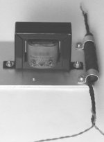
The distance between my CM choke (on the right) and the OPT is one inch. Too close? Fields are opposite though.
I must admit that I haven't done much reading on the conditions where lifting the heaters is beneficial. It's effectiveness probably depends on the signal levels being amplified?
Attachments
Hi Gab,Gabdx1 said:Split the rectifiers, Use 1N5820, put a resistance (wirewound -- this will filter high frequency and protect from surges) in serie of around 0.5 R 5W, put // cap of 10F, use shielded wires, there will be no hum problem from the heaters for sure !
Usually the hum from heaters would be 60 hertz - 120 hertz, 35 hz. Did you mesure it ?
All this is theoretical as I didn't finish this small power amp yet.
I anticipated RF contamination across the heater to cathode capacitance by implementing a common mode choke made of a ferroxcube bar. The heaters will be HF terminated by small caps to ground.
Lifting the heaters is done when the cathode is at a high potential, to lessen the stress on the isolation, right? Now I wonder if elevating the heaters in the B+ might contaminate the latter with the noise originating from the rectifiers cathode, as they share the 6,3V winding.
disco:
That's good forethought. Can't be too careful.
Lifting the heaters when the cathode is at high potential is a very very good idea. If for no other reason than to satisfy tube maximum ratings on the heater-cathode insulation.
There is a more subtle reason, though, even for tubes that have their cathodes very near ground potential. The idea is to 'bias' the heater voltage to a positive DC reference voltage with respect to the cathode. The goal being to keep the heater voltage always positive wrt the cathode, preventing a pseudo- forward biased diode behavior. This has been known to decrease hum when using AC heating (and possibly DC heating, IDK). This DC reference should have a reasonably low impedance to ground from 5Hz and up.
This has been addressed in many threads here, and is also discussed in RDH4 and Morgan Jones' Valve Amplifiers.
Maybe I should clarify that in post #3 I did state that I'm not emphatic that shielding heater leads is necessary, but that IF you are going to do it, there is an optimal way. I choose to do it only to reduce the risk of RF contamination.
As far as your common mode choke, if you don't hear or measure any hum pickup, then you're golden. I had issues with my phase splitter transformer picking up the field from my common mode choke, and had to remove it. Tight quarters, and probably wasn't necessary for my application. Dedicated split bobbin xfmr, shielded twisted pair, ceramic caps was sufficient.
I have attached a schematic of what I'm talking about. The reference divider is found with R11, R12, and R13. The +35V is for elevating the 12AT7 heater, and the +165V is for the 6N6P.
Attachments
- Status
- This old topic is closed. If you want to reopen this topic, contact a moderator using the "Report Post" button.
- Home
- Amplifiers
- Tubes / Valves
- Filament Wiring - Shielded vs. Twisted?