Hi,
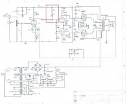
I have the following circuit from one of the commercial tube amp. It uses 1x12AX7 and 2x12AU7 as pre and the 4x 6v6GT in push pull AB1 with self bias.
I trace the circuit point by point but I cant reach the capacitor. Disregarding the power circuit for now,
1. This is Direct DC couple between 12AX7 and 12AU7. I wonder what is the connection of R8 and C3. I have no way to trace what is connected at R8 and C3 ! It seems to me R8 and C3 should be connected to B- ?
2. Isnt wise not to use direct DC couple since any fluctuation in supply will affect the sound ?
3. I identify the signal components are C5, C6, C7 and replace them with Mundorf Supreme. Besides these, what are the critical signal components ?
4. Should I change R17, R 18 and the feedback resistors to something better like Riken or Audionote tantalum ? The Negative feedback is in 2 modes, High or Low. At high, it is 680R and at Low, it is 150K, is this correct ?
5. For the negative feedback, no capacitor was used ? Is it better to have capacitor and what value and type ?
5. Should I put a grid stopper before 12AX7 with a value let say 6.8k arbitralily?
Attachments
It is an oscillation harnessing thingie. It is probably 10K and 33 pF?
When feedback is deep the amp has wide frequency band, but starting from some frequency phase shift is 180 degrees, and if a gain through a feedback loop is more than 1 on this frequency the amp starts oscillate generating radio waves.
What does that R-C Zobel network, it lowers an amplification factor on frequencies below that one on which phase shift is 180 degrees, so where phase shift is 180 degrees an amplification factor is below 1, so oscillations don't occur.
The amp is good, should work fine.
It is an oscillation harnessing thingie
I dont quite get what u say.
I found changing C5 from stock cap to Mundorf supreme really helps alot in the sound. I wonder if changing the resistors will help to improve the sound.
I am using Mullard CV series tubes while the 6v6gt is tungsol reissue. Guitar acoustics really rocks.
ccschua said:
I dont quite get what u say.
I found changing C5 from stock cap to Mundorf supreme really helps alot in the sound. I wonder if changing the resistors will help to improve the sound.
I am using Mullard CV series tubes while the 6v6gt is tungsol reissue. Guitar acoustics really rocks.
It the cap was dead changing it you've stopped oscillations. The RC network compensates the amp on high frequencies that are unaudible, otherwise it oscillates on high frequencies with feedback applied.
If you put much bigger value of the cap you could roll-off highs on audible frequencies.
Frank Berry said:R8 and C3 may be for power supply hum reduction. What are the values of R8 and C3?
A 1k grid stopper on the 12AX7 won't hurt but if it wasn't in the original design, it may not be necessary.
It looks to me R8 and C3 serve to add Bias to Grid of V3A ? I think I will measure the DC condition and if necessary, dismantle the board for the capacitors connection.
Hey guys - listen to Wavebourn, he is giving you the real answer.
R8 and C3 are a absolutely typical "zobel" or "step" network to stabilise the amplifier when global feedback has been applied - as in the case with this amplifier. Don't let R6 fool you. Remember that the power supply is effectively at signal (AC) ground, it is tied there by those big electrolytic bypass caps (C10 in this case). So as far as AC or signal is concerned that R8 and C3 could just as easily been tied from the 12AX7 anode to 0V. It makes no difference to their operation.
As you go higher in frequency the output transformer introduces phase shift. At ultrasonic frequencies the phase shift through the output transformer can be enough that the negative feedback (from the output tranny secondary) becomes positive feedback. If the amplifier gain at this frequency is more than 1 then it oscillates. R8 and C3 reduce the gain at high frequencies (while leaving the phase response largely unmodified) such that at that frequency where the feedback becomes positive the gain has been reduced to less than 1 and so the amplifier remains stable rather than oscillating.
Semi technical bit (leaving aside the vector algebra and talking a bit loosely): - Skip if of no interest
Gain of an amplifier (open loop or no feedback) is found by multiplying the gains of each stage together.
Gain of that input stage is proportional to the anode load - 100K in this case.
As frequency goes up the impedance of C3 drops and starts to reduce the gain - when Xc (the capacitor impedance) is approximately 90K then R8 + C3 = 100K and the effective anode load is then 2 x 100K in parallel or 50K and the gain will be halved. As frequency continues to go up Xc continues to go down and gain continues to be further reduced until Xc becomes insignificant and the 10K (R8) dominates the anode load.
However significant phase shift is not introduced until Xc falls to 10K (the R8 value) or below. When Xc = 10K there will 45 degrees phase shift. This happens at a frequency 9 times higher than the 1/2 gain point.
So a zobel or step network basically reduces high frequency gain while leaving the phase untouched until very much higher frequency - just what is required for stabilising the amplifier when global feedback is applied.
The values of R8 and C3 Wavebourn suggests (10K and 33pF) are typical and in the right "ball park". For correct zobel opperation teh resistor (R8) needs to be approximately 1/10th of the value of the load resistor (100K). C3 sets the frequency at which gain starts to roll off. If the amp still oscillates make it bigger.
You asked, "how can +150V go to the grid of the 12AU7?". For a typical bias of say -10V from grid to cathode of a 12AU7 that means that the cathode is sitting at +160V. From that you can work out that there is 7.3mA current flowing through that 22K cathode resistor on the 12AU7, or 3.65mA per side of the 12AU7 differential driver (160V divide by 22K = 0.0073 Amps).
Cheers,
Ian
Thks for your reply. It makes ssense to me now, cause I dont really see such network in the old 'typical' tube amp.
As for the global feedback, the adjustment allows for 680ohm or 150K. I 'normally' see a capcitor of 100p to 1000p added in paralle to the resistor. what is that use ? improve high frequency ?
As for the global feedback, the adjustment allows for 680ohm or 150K. I 'normally' see a capcitor of 100p to 1000p added in paralle to the resistor. what is that use ? improve high frequency ?
The capacitor across the feedback resistor also helps with stability.
As we have said, at higher frequencies the output transformer delays the signal a bit, what we call a phase lag.
The capacitor across the feedback resistor is generally called a phase lag compensation capacitor. It allows high frequencies to bypass the resistor a little, speeding up the high frequency component of the feedback from the secondary of the output transformer (that is, working against what the transformer has already done by delaying the high frequencies). Generally, this capacitor is the last thing you set in a design. It is set by experiment. Once the amp is all working and is stable with feedback applied, you look at a 5 or 10kHz square wave into a dummy resistor load (instead of a speaker) using an oscilloscope. You then add capacitance across the feedback resistor (this phase lag compensation cap) to get rid of any major overshoot or ringing on the top and bottom of the square wave.
Hope this makes sense.
Cheers,
Ian
surprise surprise. I trace the circuit further and made a measure at idle without any input.
Hope the gurus can help out the newbie here.
1. apparently the R8 and C3 is not used.
2. Capacitor Ca at V1 12AX7 cathode is not used. So the Bias condition changes with input signal? Is this good?
3. The biasing condition for V4,V5 (6V6GT ) shows it is bias in class AB (21V/680ohm x 2 = 61mA). Is this correct ?
4. Are the biasing for V1a and V3a and V3b correct ? what should be the correct level ?
5. This is a direct DC couple. Is it better than compared to using a coupling cap to isolate V1a (12ax7) and V3a ? (12au7)
Overall what is the drawback of this design ?
An externally hosted image should be here but it was not working when we last tested it.
Hope the gurus can help out the newbie here.
1. apparently the R8 and C3 is not used.
2. Capacitor Ca at V1 12AX7 cathode is not used. So the Bias condition changes with input signal? Is this good?
3. The biasing condition for V4,V5 (6V6GT ) shows it is bias in class AB (21V/680ohm x 2 = 61mA). Is this correct ?
4. Are the biasing for V1a and V3a and V3b correct ? what should be the correct level ?
5. This is a direct DC couple. Is it better than compared to using a coupling cap to isolate V1a (12ax7) and V3a ? (12au7)
Overall what is the drawback of this design ?
I think it's not too bad. It's almost identical to one of the first amps I ever built ")
My noob observations:
1. R8 and C3 don't make sense where they are located, so it's a good thing they aren't used. However, the R5 and its cap look to be incorrect. Perhaps the common actually ties to the plate of V1a, so you have a series RC in parallel with R4? Double check that.
2. Removing Ca increases local feedback on the first stage (which is what I had, too). A little local feedback on the non-perfect AX7 is not such a bad idea IMO. It reduces the loop gain, which will also affect the amount of global feedback (Rf1,Rf2) you will need. So the feedback may need to get some attention. Personally, I would leave Ca out.
3. 61mA total for the pair, yes. You are saying there are two 680 ohm resistors in parallel?
4. I think the voltage is a little low on V1a, which is most affected by that low +B3 you have. Reduce that 220k resistor to increase +B3. Maybe shoot for 1mA or so. V3 bias is determined based on the DC plate voltage at V1a, divided by the tail resistor R12. If you put in a CCS in place of that tail, you fix your idle current in that stage. Might be an improvement. R13 and R14 should then be equal.
5. I don't know about better, but it is required given your existing topology. That DC coupling affects the biasing of the next stage. As above, though, I suggest that plate voltage be increased.
1. R8 and C3 don't make sense where they are located, so it's a good thing they aren't used. However, the R5 and its cap look to be incorrect. Perhaps the common actually ties to the plate of V1a, so you have a series RC in parallel with R4? Double check that.
As pointed out earlier, R8 and C3 is feedback stabilization thing (by Wavebourne). You are right that R5 series with tiny little ceramic cap parallel with R4. What is the purpose of this ?
agree2. Removing Ca increases local feedback on the first stage (which is what I had, too). A little local feedback on the non-perfect AX7 is not such a bad idea IMO. It reduces the loop gain, which will also affect the amount of global feedback (Rf1,Rf2) you will need. So the feedback may need to get some attention. Personally, I would leave Ca out.
yes. 680ohm is the cathode resistor both in parallel.3. 61mA total for the pair, yes. You are saying there are two 680 ohm resistors in parallel?
4. I think the voltage is a little low on V1a, which is most affected by that low +B3 you have. Reduce that 220k resistor to increase +B3. Maybe shoot for 1mA or so. V3 bias is determined based on the DC plate voltage at V1a, divided by the tail resistor R12. If you put in a CCS in place of that tail, you fix your idle current in that stage. Might be an improvement. R13 and R14 should then be equal.
I have to add that V3 cathode bias is 73Vdc which means 1.6mA for each of V3a and V3b.
V1 and V3 bias changes as audio signal is present. Is it too low a bias at V1 affects the distortion ?
What is your recommended value to change the 220k? how about 1.5mA for V1 ?5. I don't know about better, but it is required given your existing topology. That DC coupling affects the biasing of the next stage. As above, though, I suggest that plate voltage be increased.
flysig said:3) 21v is textbook AB1 biasing for 6V6GT guitar amps.
Yes. I am doing about 31mA per tube. Increasing it to 50mA i.e. at cathode voltage of 34V would give any advantage ?
ccschua said:You are right that R5 series with tiny little ceramic cap parallel with R4. What is the purpose of this ?
This sets a dominant pole so the amp is stable with feedback. The idea is to limit the open loop gain at higher frequencies to prevent oscillation and/or ringing. You use a 1 or 10kHz square wave input, and tweak the RC for optimal response (minimal to no ringing with best rise time possible). One can also experiment by adding some capacitive loading to ensure stability. Somewhere on this forum someone had presented a mathematical argument to show the optimal R value is 1/10 the value of the plate load. It's what I use, and works great. I'm sure the 4.7k will be just fine, so you just need to play with the C value. I recommend a mica cap in the values you should expect.
V1 and V3 bias changes as audio signal is present. Is it too low a bias at V1 affects the distortion ?
Well, the DC idle conditions will be unchanged as the signal is applied. The AC voltages and currents will change with signal; that's how the amp works. If the grid voltage is too small, you will end up drawing grid current during positive peaks of your music, so you need to look at what your input source is driving. Am I not understanding your question?
What is your recommended value to change the 220k? how about 1.5mA for V1 ?
Thing is, as mentioned above, the first two stages are dependent on one another, as the stages are DC coupled. So once you change this resistor (or just about any resistor), the idle conditions for both stages are affected. Change the plate voltage of the AX7, you modify the current through the LTP. You would want to go back through the whole amp and analyze each stage, where you want it. Might be a good exercise for you. But you can't just change one resistor and expect everything else to fall into place.
V3 is the long tail pair with R12 the tail resistor. If change to CCS, what would be the transistor type ? cascode constant current source?
Sure, why not? BJT or depletion FET would be fine. There are numerous designs to be found in this forum. Changing to CCS was a major improvement in my amp. Hand match those plate loads, and away you go.
Your advice is very consistent with the way tube amp is designed. I would appreciate if you can help identify on the circuit which are the signal path resistors.
My guess is all the resistors are on signal path but R17 and R18 being the greatest, right ? But I think rather than spending money on components, might as well work straight on the design of CCS.
When R12 is replaced with CCS (say 2sk117 GR), what sort of matching required for R13 and R14 ?
As to the changes in the biasing resistor, I think a simulation on microcap will help right.
Now you are getting into territory that is very much opinionated, that of component selection. Obviously, you need to determine what value there is to 'upgrading' components in an amp such as this. As a builder/owner of an amp very very very similar to this, all I can do is give you my opinion. This is not a mega ultra quality amp. It uses feedback, which makes it less stringent on parts quality. Therefore:
Put 1K carbon comp grid stoppers on every grid you see, with the resistor body as close to the pin as you can.
Metal film resistors are just hunkey-dorey, no need to 'upgrade' to exotic resistors. Pay close attention to voltage and wattage ratings, which may necessitate the use of WW resistors. Consider a quality non-inductive resistor for Rf, maybe Caddock or some other film/foil type, but don't spend more than $5 each. I don't mean a resistor blessed by the Dalai Lama, I just mean a reputable type. You can do your experimentation/debugging with cheap metal films until you find the optimum value, then buy the quality resistor.
Don't bother with exotic capacitors. I installed Mundorf something or the other for C6 and C7, cost me around $30 each from Madisound. Made ZERO difference in sound quality. Wima shall do thee just fine, metallized or foil polypropylene. Maybe 715P/716P Orange Drop. Save your $$$$ for your next amp !!
Since you are not spending mega-bucks on resistors, buy a couple extra and hand-select matched pairs of the following: R13,R14 and R15,R16. Possibly the feedback resistor as well, since that will control your left-right gain to a large extent.
If you have a reliable simulator, by all means use it. Even if it doesn't predict the THD, at least getting reliable idle conditions it a big time saver.
I have attached my favorite CCS for your viewing pleasure. PERFECT in a LTP like yours:
http://www.diyaudio.com/forums/showthread.php?postid=1725776#post1725776
LLT !!!
Long Live Tubes !!!
ccschua said:Yes. I am doing about 31mA per tube. Increasing it to 50mA i.e. at cathode voltage of 34V would give any advantage ?
Biasing down to 34 v will get your tube pretty much into cutoff. That takes you out of AB1 and I believe makes it much more critical to get the biasing matched between tubes. It would give you more headroom, meaning that a larger input signal can be tolerated before going into distortion in the output tubes. But it means more tweaking to get it balanced and also you would have to rebalance it when replacing the tubes. I don't have the experience to tell you about the differences in sound or other considerations.
- Status
- This old topic is closed. If you want to reopen this topic, contact a moderator using the "Report Post" button.
- Home
- Amplifiers
- Tubes / Valves
- 6V6 PP AB1 circuit