I have a power transformer with an extra 550V CT winding that I would like to use as a bias supply for Poindexter's EL34 Music machine. I'm assuming that I can use one half of this winding with a couple of resistors to derive the appropriate (-50V) bias voltage. The 550V CT winding is rated for 40ma.
How much current should I design this tap to source? If I use a relatively low R voltage divider to allow for some current, the resistors burn a lot of power. What's a typical design grid current for fixed bias trioded EL34's?
How much current should I design this tap to source? If I use a relatively low R voltage divider to allow for some current, the resistors burn a lot of power. What's a typical design grid current for fixed bias trioded EL34's?
parts of microamps
its a bias voltage, not bias current. Set to run real low current across the divider - 1 or 2ma will be fine. There is effectively NO current from the bias supply to the tube grid. A 550V, 40ma trannie is overkill!!! Hope you are doing something else with it!
its a bias voltage, not bias current. Set to run real low current across the divider - 1 or 2ma will be fine. There is effectively NO current from the bias supply to the tube grid. A 550V, 40ma trannie is overkill!!! Hope you are doing something else with it!
Re: parts of microamps
I'm using it for the power tranny, as it has a 720 CT @ 100ma also. I'm building monoblocks, and I have 2 of these. So no current capability is OK? none, zero, nada? Just supply the volts?
aardvarkash10 said:A 550V, 40ma trannie is overkill!!! Hope you are doing something else with it!
I'm using it for the power tranny, as it has a 720 CT @ 100ma also. I'm building monoblocks, and I have 2 of these. So no current capability is OK? none, zero, nada? Just supply the volts?
current always matters.
if you want -50 and you have 275 to work with you are going to be dropping a lot of voltage on the converter - and the amount of current had better be static (not variable) or a voltage divider won't give you what you want.
If you use a DC to DC be prepared for a massive heat sink.
standard disclaimers apply")
V=IR, its the law.
if you want -50 and you have 275 to work with you are going to be dropping a lot of voltage on the converter - and the amount of current had better be static (not variable) or a voltage divider won't give you what you want.
If you use a DC to DC be prepared for a massive heat sink.
standard disclaimers apply
V=IR, its the law.
correct boy wonder
whilst strictly correct, the old man is a little off subject imho. Your grid bias is effectively a voltage only issue - within the bounds of the normal grid leak resistor limits etc. I'd aim for a total resistance in the divider network of around 1/2meg (giving around 1ma current through the network and 0.5w dissipation), with the grid leak resistors at around 200k. Never worked with EL34s though, so I'm happy to be contradicted - its all a learning experience!
At worst, you will find the resistance is too high and you have to change four resistors - so what?
If you want to design it right, look at your max grid leak spec and consider what will happen if you have a tube that is pulling a little grid current. Your resistor divider has an output impedance that that appears in series with the grid leak resistor. That output impedance could be significant if you are dropping lots of volts in the divider and using large resistors.
Or you could drive the EL34s with MOSFETs and apply the bias voltage to the gates of the FETs through 10M or so. With FETs it really is just a voltage issue, tubes only nearly so.
Or you could drive the EL34s with MOSFETs and apply the bias voltage to the gates of the FETs through 10M or so. With FETs it really is just a voltage issue, tubes only nearly so.
Thanks for the input, time to do a little more breadboarding.
Got it, I'll check the max grid leak spec for fixed bias triode connection.
Sounds great, but still over my head. Without a schematic, I'm still at ohm's law and voltage dividers.
SpreadSpectrum said:If you want to design it right, look at your max grid leak spec and consider what will happen if you have a tube that is pulling a little grid current. Your resistor divider has an output impedance that that appears in series with the grid leak resistor. That output impedance could be significant if you are dropping lots of volts in the divider and using large resistors.
Got it, I'll check the max grid leak spec for fixed bias triode connection.
SpreadSpectrum said:
Or you could drive the EL34s with MOSFETs and apply the bias voltage to the gates of the FETs through 10M or so. With FETs it really is just a voltage issue, tubes only nearly so.
Sounds great, but still over my head. Without a schematic, I'm still at ohm's law and voltage dividers.
mosfets are easy peasey boywonder
check this out www.geofex.com/Article_Folders/mosfet_folly/mosfetfolly.htm
Treat it like a cathode follower triode. Does need a separate bi-polar power supply, but you have that to hand anyway.
check this out www.geofex.com/Article_Folders/mosfet_folly/mosfetfolly.htm
Treat it like a cathode follower triode. Does need a separate bi-polar power supply, but you have that to hand anyway.
Finally getting to the point where the solder meets the iron...
I am finally building up my mono 6GK5/EL34 triode Music Machines, and I am still struggling with the bias supply design. I would like to use the extra 240V/40ma winding on my PT mentioned above with a voltage divider to get the -50V neg rail for the fixed bias, but I am concerned about the output impedance, ie it will be very high compared to the separate transformers that Poindexter has spec'd.
Poinz is specifying 44V transformers that are rated for around 32ma for the mono application, and 70ma or so for the stereo application. To keep the heat reasonable for the voltage divider R's, the extra winding I have will be capable of providing a couple of ma at best.
So, my basic question is: How many milliamps will the bias supply be expected to supply for a pair of triode connected EL34's? I am sure there is a reason that Poinz is specifying 32ma/70ma bias transformers, I just don't know what the reason is. The discussion above (which makes perfect sense to me) says that pretty much no current is needed (ie AB1). So is the bias voltage really just a voltage, with no need to provide any current?
My fear is that if the tubes need ma that the supply cannot provide, they will run away....
contact poinz - he's generally more than accommodating with even my dumb questions...
will do, thanks
So, my basic question is: How many milliamps will the bias supply be expected to supply for a pair of triode connected EL34's? I am sure there is a reason that Poinz is specifying 32ma/70ma bias transformers, I just don't know what the reason is. The discussion above (which makes perfect sense to me) says that pretty much no current is needed (ie AB1). So is the bias voltage really just a voltage, with no need to provide any current?
My fear is that if the tubes need ma that the supply cannot provide, they will run away....
Max grid circuit resistance is the spec you need to look at. I don't think of it as "how much current do I need," it is better just to take your bias divider into account in calculating the grid circuit resistance. You should definitely be able to come up with something that will work fine with your existing transformer.
Most people ignore the bias network and just set their grid leak to the max value. If you have a high impedance network to derive your bias voltage you can get into trouble. The solution? Lower the impedance of the network, which will burn some power if you have excessive voltage to burn off. I like those TO-220 thick film power resistors for that. Just bolt them to an aluminum chassis and they don't even get warm in most cases.
Bias solution
There are a lot of solutions here, but here is mine - also useful when there's no bias winding at all:
Search for a tiny wall-wart transformer at about 18-24V. Open it (or break if it's sealed) and use only the transformer. Connected in reverse (the original 24V secondary as new primary - so a raising voltage transformer) from the 6.3 filament winding you will get a secondary voltage which is a fraction of the original 230V - in our case, for 24V "primary" the resulting voltage will be (6.3:24)*230V=60.3V. More suitable...
For the 115V network a 9-12V trafo will work fine.
The transformer has to be small, his power is not important - even a little PCB trafo will be ok - and there will be no extra heat at all...
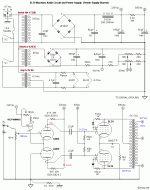
Here is the schematic:
So I should add the upper R from the voltage divider to the 390R + 27K R + 10K pot R (in parallel with the 22K R) + 150K grid leak R and make sure that these sum to less than the max allowable grid leak spec? Is the max grid leak spec different for triode vs UL vs pentode? I cannot find and datasheets for fixed bias triode for EL34, so that is where the above question comes from.
I imagine that I actually need to solve for the upper voltage divider R by setting the above values = max grid leak spec, and possibly stay below that value, then see what kind of power will be dissipated........
Attachments
Your resistor divider has an output impedance that that appears in series with the grid leak resistor. That output impedance could be significant if you are dropping lots of volts in the divider and using large resistors.
Yes, that is very important though often ignored.
If I have read properly, nobody has yet suggested a capacitor for the voltage dropping component - no heat dissipated. It will have to be a high voltage component (>600V Boy Wonder? You started by mentioning 550V ct, which is 275V either side of the centre tap, then you mentioned 240V. No problem, the cap voltage just has to be able to handle the peak voltage + say 15%.)
The series impedance would still be high, thus some form of protection (zener diodes across the output of a bridge rectifier) would be prudent. The value would be around 0,018 - 0,056µF depending on other factors.
Aardvark and SpreadSpectrum have given the pertinent data, in my view.
The voltage divider to ground should draw about 1mA of current, so that if you start with, say, 50Vdc at the first cap, net resistance (including the adjust pot for each channel) would be on the order of 50K. This will keep the voltage at the takeoff point stable. From here, a resistor equal to or less than the Rg-k rating will go to the grid(s) of the tube(s). This will keep the voltage at the grid stable. If you use a known gassy tube like a G.E. you may want to go a little lower on the Rg-k.
I myself wouldn't divide down a 550V rail to get the ~30V for an EL34 grid. You going to be burning over half a watt in that divider, a pretty good source of heat inside the chassis. I would get a little Amveco 22+22 toroid, a 62025 or so, and build a supply from that. They're little. Last time I talked to John, Antek were moving into the smaller ratings as well, so they might have something too.
Aloha,
Poinz
AudioTropic
Continue ...
Sorry Boy Wonder, did not see your last post - we have typed at the same time!
Your diagram did not come out clearly on my screen, thus I could not judge. My suggested capacitor is of course before the rectifier. I also forgot to mention, although it might not be relevant here, that one must remember that resistors also have maximum voltage ratings. One cannot e.g. use one 1 meg resistor in series with say 700V - they micro-flash through between windings/spirals and burn out. Normally 300 - 400V is the limit for 0,5W types - the specs are available.
Thanks everyone!
Johan: Sorry for the confusion, the tap that I have to work with is 550VCT; it's sitting here right in front of me. I'm not quite clear on the use of a cap, but it sounds interesting.
Poinz, Aardvark, Spreadspectrum-thanks, I'm getting it.
I found a "limiting value" of .7meg (for A and AB) and .5 meg (for B) for max grid leak in the Philips data sheet, although the other data for triode is all for cathode bias....hopefully this is correct. I'm assuming that this value doesn't change for triode, UL, etc....
- Status
- This old topic is closed. If you want to reopen this topic, contact a moderator using the "Report Post" button.
- Home
- Amplifiers
- Tubes / Valves
- Bias supply and grid current