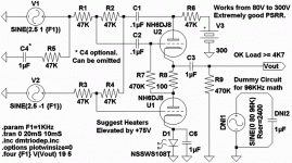
Differential White Cathode Follower for DAC
Twin triodes simultaneously doing THREE jobs very well:
With resistors R3&R4, this cascode acts as a unity gain
inverting plate follower.
With resistors R1&R2, this cascode also acts as a White
Cathode Follower of the average voltage. (V1+(-V2))/2
The output voltage swing may be small, but impedance
is both extremely low, and very symmetrical.... You can
definitely drive difficult loads.
The combined error correction signal at the top plate is
so strongly controlled, it tends to overwhelm any power
supply noise. You won't see any PSRipple in the output.
So its sort of its own smoothing regulator too...
-----------also note-----------
V1 sees 47K to virtual ground (between R3&R4)
V2 sees 47K to signal ground, and a very high
impedance across R1&R2 to the plate follower.
Assuming both inputs are truly differential, this
plate holds a duplicate copy of a similar signal.
So both inputs seeing the same 47K impedance...
Attachments
Very nice, I always wondered what I would do with a current mode
DAC. What's the CMRR? Or does it matter? Common mode impedance
is low.
"What weird circuits have you been dreaming lately?"
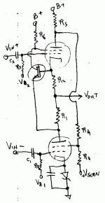
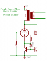
Who, me? Why are we all playing with cathode followers?
Augmented cathode follower of some kind. Anti-signal current mirror
on the botton, cascode-ish follower on top to maintain constant plate
voltage. Zout ~= 1/(2*gm) or can be configured for Zout ~= 1/gfs of
the P-MOSFET if you want a flat load line.
Michael
DAC. What's the CMRR? Or does it matter? Common mode impedance
is low.
"What weird circuits have you been dreaming lately?"
Who, me? Why are we all playing with cathode followers?
Augmented cathode follower of some kind. Anti-signal current mirror
on the botton, cascode-ish follower on top to maintain constant plate
voltage. Zout ~= 1/(2*gm) or can be configured for Zout ~= 1/gfs of
the P-MOSFET if you want a flat load line.
Michael
Attachments
I have nothing to brag;
just an ordinary pentode on MOSFET steroids:
http://www.diyaudio.com/forums/attachment.php?s=&postid=1819141&stamp=1241463993
just an ordinary pentode on MOSFET steroids:
http://www.diyaudio.com/forums/attachment.php?s=&postid=1819141&stamp=1241463993
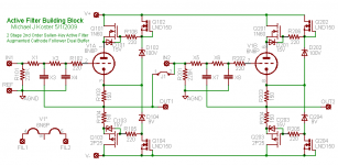
Michael Koster said:I forget... Did we do this already?
Fixed cathode bias regulator with current mirror for a 2X improvement
in damping factor, LF extension, output power...
This is very raw, just a concept.
To do:
Temp stability? Vgs = Vg1-k?
Edit: however, power tubes have higher Vg1-K than Vgs is needed, so my concern is not valid.
Variant: large emitter under MOSFET than under a tube.
Variant 2: different resistors in emitters.
PS: I've finished soldering a prototype, am afraid to switch it on and find hidden surprises, so am reading the forum for a while...
Hi Anatoly!
Go, switch on the barracuda!!
Just to see if I got it: current through the 12L6 will develop a voltage over R6. Substract the voltage drop of the mosfet (about 4V?) from the voltage over R6, and divide the obtained value through the amount of current desired through the mosfet, to determine R8.
R5 is used to provide the cathode-bias, R7 to measure standing current...
Michael Koster said:I forget... Did we do this already?
Fixed cathode bias regulator with current mirror for a 2X improvement
in damping factor, LF extension, output power...
Papa patented that
Wavebourn said:I have nothing to brag;
just an ordinary pentode on MOSFET steroids:
http://www.diyaudio.com/forums/attachment.php?s=&postid=1819141&stamp=1241463993
Great! You could probably use a variation of the garter balancer with that.
What happens with screen current?
Michael
Michael Koster said:
Great! You could probably use a variation of the garter balancer with that.
What is garter balancer?
What happens with screen current?
As usual, I use it in an opto-compressor.
")
That thingy drawn gave me 300W with 170V B+ driven by a plain and easy Concertina splitter.
Zen Mod said:
Papa patented that
One more path in the forest had been named, and a fee paid to protect it from free usage by other people.
"That thingy drawn gave me 300W with 170V B+ driven by a plain and easy Concertina splitter."
Oh, class AB. Yeah, these things work fine in class AB. But the balancer
is for class A I think. Maybe the balancer plus the cathode clamp...
"One more path in the forest had been named, and a fee paid to protect it from free usage by other people."
One more piece of poop legally documented, labeled, and classified! Watch
out!
A patent used to be a good thing, protecting the poor inventor from being
ripped off and exploited by bigger playground bullies. Now the bullies have
taken over the patent system and use them as sticks. You have to get
patents in your own defense.
I say it should go like trademarks, use it or lose it. Except no 100 year
extensions like the one they did for Mickey Mouse.

Michael Koster said:So in this case it is protecting the inventor from corporate bullies,
and the invention is being used in the inventor's products.
Also without a citation it was hard to tell... I'd like to look it up.
Michael
go here : http://www.pat2pdf.org/
look for 5343166
Zen Mod said:
Interesting!
But the only things in common with the circuit I published are it's
use of a cascode and a parallel circuit path for bias current.
I should explain the circuit operation a bit more.
The device above is an active current mirror for the current in the
vacuum tube, and optionally provides a fixed elevated cathode bias.
The circuit has 1/2 the Rp of the tube alone and 2X the gm for
equivalent mu.
The objective of the circuit above is to enable the use of high
impedance tubes like the 801A with "reasonable" output iron,
and resulting in a "reasonable" damping factor. It's basically
a substitute for 2 tubes in parallel.
I don't know of a circuit just like that one, but it wouldn't surprise
me if it had been done in the 1960s.
Cheers,
Michael
ErikdeBest said:Hi Anatoly!
Go, switch on the barracuda!!
Just to see if I got it: current through the 12L6 will develop a voltage over R6. Substract the voltage drop of the mosfet (about 4V?) from the voltage over R6, and divide the obtained value through the amount of current desired through the mosfet, to determine R8.
R5 is used to provide the cathode-bias, R7 to measure standing current...
You got it right, Erik.
Also, R7 is needed for better stability of idle current.
Now, guess why 170?
Edit: no, it was not Barracuda I was afraid to switch om... It was a Pyramid 7 modified. As I was afraid of, it started oscillating on 300 Khz, and I am going to revert it back...
- Status
- This old topic is closed. If you want to reopen this topic, contact a moderator using the "Report Post" button.
- Home
- Amplifiers
- Tubes / Valves
- Greatest circuit ever (or weirdest)