Hi,
I found this article on the web :
http://www.radiomuseum.org/forum/the_trioderizer_a_solid_state_triode.html
Could it be so simple ? I would like to have your feedback
Regards
Zig
I found this article on the web :
http://www.radiomuseum.org/forum/the_trioderizer_a_solid_state_triode.html
Could it be so simple ? I would like to have your feedback
Regards
Zig
ssabaud said:Hi,
I found this article on the web :
http://www.radiomuseum.org/forum/the_trioderizer_a_solid_state_triode.html
Could it be so simple ? I would like to have your feedback
Regards
Zig
Cool! I haven't got around to curve tracing the Schadeode yet,
but that's what I expected to see.
http://www.diyaudio.com/forums/showthread.php?s=&threadid=135052&highlight=
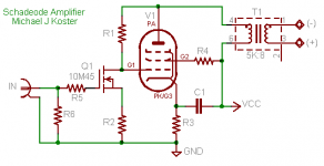
I call it the Schadeode in honor of O.H. Schade who was the first
I'm aware of to publish a description of turning a pentode or
tetrode into a triode characteristic by the use of plate-grid
feedback.
http://www.pmillett.com/tubedata/beam_power_tubes.pdf
Cheers,
Michael
Yes, it is so simple. FETs are very similar to tubes. However, parallel feedback by voltage results in input resistance that depends on an amplification factor that depends on load resistance. It is not so simple. Also, MOSFETs have higher non-linear capacitances than tubes.
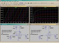
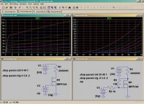
Earlier today I finished curve-tracing sims to show the similarity between MOSFETs and pentodes with reference to Schade. I used IRFP240 and EL84 to show and verify.
Will publish them later today when I am at the right computer.
The main problem, as I see it, is the input series resistor of the shunt feedback in combination with the input-capacitanace of the device. As Wavebourn says MOSFETs have bigger problems as they have non-linear capacitances (with the already high steady).
Nelson Pass used this concept in his Zens but had to go down to ca 1kohm resistors to get good enough bandwith. Wonder if he had read Schade before...........
About pentodes its not that bad but my Schade-sims of a upcoming 6AQ5 SE with gyrator-loaded 6C45 tells me the seriesresistor should not be bigger than 15k.
I think the capacitance issue can be mitigated by using a FET for the
input with the source on the input resistor or equivalent because
the Ciss will be bootstrapped by the varying voltage drop across
the resistor, and the feedback resistor can be made small enough
to drive the gate of the output MOSFET. IF you don't want 1/Gfs
for your Rp equivalent, there will also be a source resistor to bootstrap
the Ciss of the output FET.
I sort of like the idea of a MOSFET input and a pentode output.
Michael
Attachments

- Status
- This old topic is closed. If you want to reopen this topic, contact a moderator using the "Report Post" button.
- Home
- Amplifiers
- Tubes / Valves
- The Trioderizer