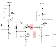
Hi, I was wondering if the components marked with red on the schematic are necessary or am I being redundant? I do not know if the tone stack would provide the necessary DC coupling and ground reference to make the red components unneeded. Any help would be appreciated.
Thanks
Scott
Thanks
Scott
Attachments
Of course !!billr said:the 12ax7 needs a grid resistance of about 1 meg, have a look at the specs and you will see this. I would leave it in.
billr said:the 12ax7 needs a grid resistance of about 1 meg, have a look at the specs and you will see this. I would leave it in.
???
Kindly, which specs are you referring to? Unless 'grid leak' bias is used, where minute grid current gives the necessary grid bias with a grid resistance of some 10meg - 20meg (which can be advantageous when fed from a low impedance source), the G1 resistor to common may be anything. It does not play a role with sufficient cathode bias as no grid current would exist.
No it doesn't, if the knobs are turned all the way round the pot is shorted out, turning the grid resistor into a 2.7k on its own.
It's a dc thing for the grid, you need the 1M resistor in there, the cap blocks the parallel action of the tone controls maintaining the grid resistor to it's original value.
hope this helps.
kind regards
bill
It's a dc thing for the grid, you need the 1M resistor in there, the cap blocks the parallel action of the tone controls maintaining the grid resistor to it's original value.
hope this helps.
kind regards
bill
Bill,
Sorry but you are wrong. With a 2k2 R in the cathode circuit, the grid resistance to ground can be pretty much anything, as long as it has some resistance. One meg would be an optimum MAXIMUM value, but it can be taken dowm to zero ohms with NO problems at all.
Regards, Allen (Vacuum State)
Sorry but you are wrong. With a 2k2 R in the cathode circuit, the grid resistance to ground can be pretty much anything, as long as it has some resistance. One meg would be an optimum MAXIMUM value, but it can be taken dowm to zero ohms with NO problems at all.
Regards, Allen (Vacuum State)
billr, you state:
Why do you think so?It's a dc thing for the grid, you need the 1M resistor in there, the cap blocks the parallel action of the tone controls maintaining the grid resistor to it's original value. It's a dc thing for the grid, you need the 1M resistor in there, the cap blocks the parallel action of the tone controls maintaining the grid resistor to its original value.
We seem to have some misunderstanding here. I took it that as Jetbat suggested, both the 1meg and the cap can be taken out - not the one or the other. In that case g1 would still see a ground reference.
Wavebourn,
Correct basically, and perhaps so from your experience, but any pot that needs that should already have been replaced. In this circuit I see the 1meg purely as a reference to ground when a coupling cap is present.
Jerluwoo,
I have never seen such a spec relating to low current voltage amplifiers. In fact (as said) one way of achieving optimal grid bias especially with sharp cut-off tubes is to use a g1 resistor of up to 20 megohm, where some g1 electrons (also some very slight 'rectification' of the signal) causes some -1V to -2V to exist on g1, thereby eliminating the need for a cathode resistor. This way of 'grid leak' biasing then gives lower distortion, but only when fed from a low impedance source - it is a little like class AB2 in the case of power stages. Such operation is listed under resistance coupled data in complete data sheets for e.g. ECC83 and EF86.
The limitation in grid return resistor value is usualy applicable in cases where rather powerful voltage amplifiers or power tubes are concerned, because the closeness of g1 to a very hot cathode could cause grid emission and a run-away condition opposite to the grid-leak condition.
This is how I often used it with the predicted effect - if this is in error I need to learn!
Early on in the discussion I removed the cap and resistor. No noticeable difference, still sounded good. Then the replies to the post showed that a test was needed. Since my ear is not tuned enough to remember the sound of a circuit after 10 minutes of soldering, need to hook up a switch to A/B the circuits.
First I tried just the 1M resistor compared to the circuit without the cap or resistor. With the 1M the sound was good. When I switched it out of the circuit, it sounded the same except the low end became deeper. Somehow the 1M resistor forms a high pass filter with something. I think the high pass frequency is around 90 - 100Hz. Sounds very nice without the 1M.
Next I set it up to switch the cap and resistor in and out of the circuit and compare the results. With the cap and resistor in the circuit the sound was good again. With the cap and resistor switched out the low end sounds like it has more power and everything is clearer. The highs are more pronounced (more sparkle) and harmonics are richer across the spectrum. Seems like it might be better impedance matching (or mismatching with the 10x rule) between the two stages. It is a subtle but definite improvement with the cap and resistor removed.
Allen, would a 1.5k cathode resistor be the same as 2.2k in regards to "the grid resistance to ground can be pretty much anything"? I am going to be trying different gains in my ECC83s at some point.
Thanks
Scott
Johan Potgieter said:
???
Kindly, which specs are you referring to? Unless 'grid leak' bias is used, where minute grid current gives the necessary grid bias with a grid resistance of some 10meg - 20meg (which can be advantageous when fed from a low impedance source), the G1 resistor to common may be anything. It does not play a role with sufficient cathode bias as no grid current would exist.
have a look at the rc coupled specs, RCA handbook has them, you can also find them at www.triodeelectronics.com.
Also, morgans valve amplifiers, i have the first and third edition, also recommends them.
ray_moth said:billr, you state:
Why do you think so?
it;s just what i've read, that's all.
Johan Potgieter said:
Wavebourn,
Correct basically, and perhaps so from your experience, but any pot that needs that should already have been replaced. In this circuit I see the 1meg purely as a reference to ground when a coupling cap is present.
Johan; such ideal pots that have zero resistance between sliding contact and the resistive surface do not exist. Tubes that have zero 1'st grid current don't exist. If you've seen them, good for you.
")
- Status
- This old topic is closed. If you want to reopen this topic, contact a moderator using the "Report Post" button.
- Home
- Amplifiers
- Tubes / Valves
- Circuit help