I've got a Magnavox 196-BA amp (12AX7,6BQ5) amp that I would like to convert to a
RH84 SE amp. Seems fairly simple but I am trying to do it on the cheap and not buy any iron. I have the resistors and caps to rewire it and have reconfigured the power supply to the RH84
schematic. I left the original power supply choke in (I don't know the value as I don't have the 196-BA schematic) and my B+ is running quite high at 385 volts without a load.
Here is my question(two actually); will this value change substantially under load? Is there a cheap way of dropping the voltage down to the spec'd 300v?(a fairly high wattage resistor?).
Thanks in advance...")
RH84 SE amp. Seems fairly simple but I am trying to do it on the cheap and not buy any iron. I have the resistors and caps to rewire it and have reconfigured the power supply to the RH84
schematic. I left the original power supply choke in (I don't know the value as I don't have the 196-BA schematic) and my B+ is running quite high at 385 volts without a load.
Here is my question(two actually); will this value change substantially under load? Is there a cheap way of dropping the voltage down to the spec'd 300v?(a fairly high wattage resistor?).
Thanks in advance...
You should load that PS down before making any decisions. I bet the B+ will drop quite a bit. What rectifier tube are you using? I'm assuming you're using the 5U4, which appears to be original in the Magnavox and spec'd for the RH84. If you need to drop 10-17 more volts, you could always just swap rectifiers (to a 5R4 for maximum voltage drop). Don't run out and buy a 5R4 prior to hooking the PS to a load.
pj
www.wildburroaudio.com
edit: I was typing while Tom posted that. Heck, maybe you'll want to swap rectifiers to get up to 300V! Still gotta' try it first.
pj
www.wildburroaudio.com
edit: I was typing while Tom posted that. Heck, maybe you'll want to swap rectifiers to get up to 300V! Still gotta' try it first.
thanks for the quick responses...
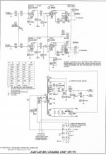
That schematic looks slightly different than the 196-BA. The first thing I noticed is that
the primaries on the output transformers on my amp don't have a center tap. There might be other small differences but we are definitely in the ballpark.
I am using a 5U4 rectifier as spec'd but I do have a 5R4WGH(a mil spec 5R4) that I can try
later if my voltages are off. I should be receiving the rest of my caps and resistors today
and will build it all up and put it under load and do the good ol' "smoke" test...
I've got it up and running and it sounds terrific with these Stephens Trusonic 12" full rangers
I found recently. The B+ was a little high at 318v with a 5u4 so I tried a 5r4, which dropped it down to 299V. The original schematic for the RH84 specs 300V so I think I am close enough.
I do have one question however; On the schematic it looks like the cathode is connected to the screen but it looks like this happens internally on the tube. Is this correct or do I need to connect the two externally. In any case, it is working now so I guess that answers my question. I have only built triode amps before so this is new to me.
Cheers!
vaughn said:I've got it up and running and it sounds terrific with these Stephens Trusonic 12" full rangers
I found recently. The B+ was a little high at 318v with a 5u4 so I tried a 5r4, which dropped it down to 299V. The original schematic for the RH84 specs 300V so I think I am close enough.
I do have one question however; On the schematic it looks like the cathode is connected to the screen but it looks like this happens internally on the tube. Is this correct or do I need to connect the two externally. In any case, it is working now so I guess that answers my question. I have only built triode amps before so this is new to me.
Cheers!
The cathode is connected to the suppressor grid, or g3, not the screen (g2). which is done internally for you on an EL84
bigwill said:Could someone explain the screen winding on that magnavox schematic? As the tube pulls its plate down, the screen grid goes up?? Anti-ultralinear?
Look carefully at the schematic, and you will see the winding resistance for the side connected to the screen is very low. There are not many turns on that side of the winding. Effectively, the screen will be held very close to B+. There will be a small amount of negative feedback mixed in, probably to help linearize the puny output transformers at the bottom end.
Ty_Bower said:
Look carefully at the schematic, and you will see the winding resistance for the side connected to the screen is very low. There are not many turns on that side of the winding. Effectively, the screen will be held very close to B+. There will be a small amount of negative feedback mixed in, probably to help linearize the puny output transformers at the bottom end.
But it appears to be wired such that the screen voltage will actually rise in response to a falling plate voltage (the tube pulling harder) - positive feedback?
bigwill said:
The cathode is connected to the suppressor grid, or g3, not the screen (g2). which is done internally for you on an EL84
Ah, thanks! My terminology is off(as usual).
It still sounds great this morning. I am putting it through its paces with a wide variety of
music and it seems a perfect match for these full rangers. It makes me want to build a "boutique" version with high quality parts.
- Status
- This old topic is closed. If you want to reopen this topic, contact a moderator using the "Report Post" button.
- Home
- Amplifiers
- Tubes / Valves
- Magnavox 196-BA => RH 84 conversion