I've been semi-obsessively collecting 18GB5/LL500 horizontal output tubes, as they are cheap and have a nice tall, skinny form factor. Has anyone out there tortured them in a screen driven amp? They have nice, thick glass envelopes, and the only disadvantage that I see so far is that they need a magnoval socket. I suspect that they are fairly common in Europe, as even the domestic versions are largely made in Holland, probably by Philips. They are rated for 17.5W plate dissipation, just like a lot of their squatty duodecar siblings, but I suspect the plates can take more, as they look pretty substantial for all manufacturers I've seen so far.
I blew one of the 98 cent 6BQ6GTB's that I got in the AES sale in a most spectacular fireworks display last night, but of course the camera wasn't ready. I succeded in extracting 125 watts from a pair of the skinny 6BQ6's right before the fireworks started.
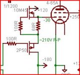
It seems that I have found a new way to blow up a tube. In extreme screen driven situations (125 watts from 6BQ6's IS extreme) the screen grid is going highly positive while the plate is approaching zero. This makes the screen grid glow. When it glows is can emit electrons which travel to the positively charged plate. The PowerDrive circuit uses a resistor to return the output (screen or control grid) to the negative supply. As the screen grid starts to draw a lot of current it is no longer under mosfet control and the screen voltage will runaway. The screen voltage rose quickly causing the tube current to shoot toward 1/2 amp. I was observing this effect and managed to catch it 3 times, but on the 4th time the fireworks erupted inside the tube and it doesn't work so good any more.
I will do some more experiments tonight!
Perhaps your screen powerdrive needs an active pulldown to survive those glow situations.
No, I really should try to avoid extracting 120 watts from a pair of tiny tubes, but I just can't help myself. I thought about building a push pull PowerDrive with active pull down, but then I realized that once the grid is glowing the tube itself is already in trouble.
I may do some experimenting along these lines anyway, but I believe this mechanism is an inherent limitation in screen drive. The screen really doesn't like being 200 volts more positive than the plate while being fed from a very low impedance source. It is probably OK for a normal music source, but continuous sine wave power testing melts grids!
I noticed the glowing screen syndrome last year, but the runaway never happened. I now realize that my wimpy power supply is what saved me. The plate and screen were fed from the same (already tapped out) source. Last night I had the plate connected to its own supply which was set on 600 volts and can source 1.5 amps.
Or turn the powerdrive upside down, so that pullup is resistive, and the MOSFET is what yanks it back toward ground...
That is what I am trying to avoid with the PowerDrive. I want to be able to slew the grid in the positive direction quickly. It is necessary for A2 operation in normal control grid drive. The pull down is only needed to discharge Mr. Miller.
Now, it is time so stop typing and hook up some fresh tubes!
I was just looking at my stash of 18GB5/LL500s last night. I like their tall, slim form factor. What I don't like is their 275V plate voltage rating. Since these are, after all, horizontal output tubes, I assume that this plate rating can be played with somewhat, especially in a screen drive context. Still, this does tend to limit the output power as compared to some of the tubes with less challenged plate voltage ratings. I may just decide to just let it rip and run a pair of these at 400V B+ to see what I can squeeze out of them in a screen drive P-P amp the peak cathode current is in line with the rest of its squatty little 17.5W brethern, so I can reasonably expect as high a peak power. Am I getting a little jaded, or does 45-60W/channel seem to be insufficient motivation to pursue a screen driven P-P design using these tubes?
Perhaps your screen powerdrive needs an active pulldown to
survive those glow situations. Maybe something like a White
Source Follower?....
Or turn the powerdrive upside down, so that pullup is resistive,
and the MOSFET is what yanks it back toward ground...
Or turn the follower upside-down and use an active pullup - allows a depletion mode FET to be used for the pullup in a mu-follower configuration. Low impedance drive in both directions.
Attachments
Did you ever try these tubes out?
I'm running an SE,UL amp with EL500/6GB5 at roughly 300v plate to cathode an 60ma.
I'm using a 2.5k output with no feedback, these things sound really really nice as well.
(it's been running on an off for about a year, very stable at these parameters anyway)
I was running 6SL7 direct coupled to 6SN7 CF, I thought with the bias voltage they'd
be a bit more difficult to drive or least need some voltage gain but the amp was "way"
to sensitive, turned out just the mu of a 6SN7 was enough gain, I also had some plate
to grid feedback in there, turned out to be better with no feedback. Quite nice tubes!
(if running conventional I'd say an mu of around 30 is a good solid voltage gain stage)
No, I really should try to avoid extracting 120 watts from a pair of tiny tubes, but I just can't help myself.
Have you tried class D yet?
Tim
I blew one of the 98 cent 6BQ6GTB's that I got in the AES sale in a most spectacular fireworks display last night, but of course the camera wasn't ready. I succeded in extracting 125 watts from a pair of the skinny 6BQ6's right before the fireworks started.
One day you're going to open up an interdimensional doorway at your bench and we'll never hear from you again

Cheers!
Have you tried class D yet?
Well, I probably shouldn't confess my sins in this forum, but I have some TAS5616DKD's on my Digikey list, and an Ebay sourced 48 volt 12 amp power supply under my bench.
One day you're going to open up an interdimensional doorway at your bench and we'll never hear from you again
But first I need to build a power supply that runs on Dilithium crystals.
Did you ever try these tubes out?
I haven't cranked any tubes into the glow zone since zapping a couple of already gassy 3D21's in conventional G1 drive (September?). It has been a few months since I have blown anything up, and that was only a capacitor. I had to remind myself that you can only put 600 volts across a 450 volt cap for a short while.
Well, I probably shouldn't confess my sins in this forum, but I have some TAS5616DKD's on my Digikey list, and an Ebay sourced 48 volt 12 amp power supply under my bench.
Nonono, class D tube.
Compound Tube Contest
Tim
Nonono, class D tube.
Yes, I followed that design as in unfolded on the Geek Zone forum. I had built a very similar design a few years earlier at work but it was all sand state. I needed a SMPS that could be modulated at a DC to 150 KHz rate with good linearity. The switching frequency was 2 MHz.
A modulated converter being used as the power supply in a high powered transmitter (for efficiency improvement) was rather cutting edge at the time. It is fairly common now. I sacrificed at least a dozen mosfets to the fire gods on that project. That knowledge was used to design a modulated power supply using a dsPIC chip that led to 30 watts from a 6AS7 in SE (class H).
I have more ideas for vacuum tube projects than I could ever possibly build, so I have to try to select projects that have some usefulness, and a reasonable probability of success.
When I have time, I am going to venture back to the dark side and blow up some sand! The last solid state audio amp that I built was 17 years ago. It was a car amp that I built as a senior project in college (at age 40). I still have the 15 inch sub from that project (the amp fried a long time ago).
Those all sound like power supply applications (I would like to read more about that 2MHz modulator though). Why not output as I did? Lots better plate efficiency. I bet you can get your 100W output without melting any plates (screens, we'll see!).
Class D isn't just for SS anymore.
Tim
Class D isn't just for SS anymore.
Tim
I may try some 18GB5/LL500 tubes with the "Bursar" transformer coupled circuit in screen driven mode if it works out driving 63PS-E tubes. Either these, or one of the many squatty doudecar horizontal sweep tubes without plate caps. The bitty plate caps on the 6BG5s are a pain in the butt, as nothing readily available fits quite right. Somehere in my stash I have some of the old wire spring-type plate clips, but they are just sudden death waiting to happen, and should only be used with tubes that are in a cage...
I would like to read more about that 2MHz modulator though
I work in an advanced development group involved in next generation wireless equipmemt for the public safety market. Things like 100 watt transmitters for cop cars. The current stuff is all secret, but the agile power supply circuitry (now common in cell site transmitters and many phones) will sound very familiar.
If you look at your class D amp, my design was a sandy version of the same:
The first 6X8 is an oscillator / ramp generator. I used a CMOS divider to divide the master 16.8 MHz radio clock down to a 2.1 MHz square wave. This alternately charges and discharges a cap through a CCS making a triangle wave. Off the shelf high speed op amps and comparators were used.
The second 6X8 is a comparator. I used a Linear Technology high speed comparator chip. The "audio input" in my case was filtered and band limited to 150 KHz. The normal input was the a propriatory modulation signal from the transmitter which contained both amplitude and phase information not unlike CDMA. Only the amplitude component is used here. I did test the whole chain with audio which lead to more experiments several years later. The output of the comparator is a pulse train at a 2.1 Mhz rate whose duty cycle is proportional to the instantaneous amplitube of the (audio) input signal.
The PWM signal from the comparator goes to a floating mosfet driver chip and a mosfet. This is so that I could use the mosfet as a high side switch in a buck convertor configuration. This is followed by several poles of low pass filtering so that the 2.1 MHz "carrier" is removed but the 0 to 150 KHz "modulation" is passed. This is used to buck a 28 volt power supply down in step with the amplitude of the transmitter modulation. This is now the power supply that runs the RF power supply in the transmitter. This way the RF power amplifier is fed just enough DC voltage to keep it linear at any moment in time. When you consider that the peak to average ratio of the modulation used was about 10 db there is some considerable room for improvement compared to just running the RF power amp on 28 volts all the time.
What does this have to do with vacuum tubes and audio? Remember the "experimentation" that came a few years later? Consider a class A single ended tube amplifier. The output tube is busy turning ALL of the energy that goes into it into heat when the volume is all the way down. When you crank a sine wave at full power through it maybe 1/4 of the energy that goes into the plate gets turned into audio and 3/4 gets burned up as heat. We can't do anything about that.
Real music has a peak to average ratio of between 10 and 40 db depending on the music and how much compression was used during recording. This means that your 10 watt SET produces about 1/10 of a watt on average. Using the technology explained above, we could build say a 1/2 watt SET that could be made into a 1 watt, 5 watt, or even a 50 watt SET in a fraction of a millisecond. How, by adjusting the power supply voltage in step with the audio signal in response to the needs of the output tube. Since the output power of a class A amplifier is usually limited by the tubes dissipation rating, this is a viable way to double or triple the output of a SET without frying any tubes!
It turns out to be a bit more complicated than that, but it can be built, and I have built one! I designed a vacuum tube amplifier using a modulated power supply using a dsPIC chip for a design contest in Circuit Cellar magazine back in 2007. The entire contest submission can be downloaded here:
Microchip 16-bit Embedded Control Design Contest
I also wrote s feature article about the design for publication in Circuit Cellar magazine. It was in their October 2009 issue.
Interesting.
The problem with class G (or however you want to call it) around tubes is the OPT. It'll work in PP pentode, because output gain depends mainly on transconductance, which is nearly independent of plate voltage. But around triodes, you have the L-R time constant of the transformer inductance working against Rp. This will modulate the speakers (PSRR is approximately *zero*!) as well as the gain (plate modulation isn't just for class C, although it has lower efficiency applied to class A). Is that something you adjusted with the dsPIC, i.e. is the audio signal not just monitored, but processed?
Tim
The problem with class G (or however you want to call it) around tubes is the OPT.....(PSRR is approximately *zero*!)
Yes, the PSRR of a typical common cathode output stage is somewhere between bad and nonexistant. That is why I use a cathode follower for the output stage. PSRR is 40+ db, and when the power supply is esentially the audio signal, that is good enough. The distortion is lower than the cathode follower by itself, since the voltage across the output tube is held constant at 75 to 100 volts (programmable). This removes any voltage related parameter shift effects.
is the audio signal not just monitored, but processed?
There is no processing on the audio at all. The audio path is all tube.
- Home
- Amplifiers
- Tubes / Valves
- 6GB5 and Variants as Screen Driven Amps