Hearinspace said:Is that what Q3 is in Michael's circuit?
Yes, but they usually have 2 legs, look like diodes, and are called Stabistors. The common name is Zener, but actually Zeners occupy their place in the middle between FET stabistors (lower voltages) and Avalanche diodes (higher voltages). Stabistors usually have lower noises than Zeners do. Michael made one from a widely available MOSFET.
http://search.datasheetcatalog.net/key/STABISTOR
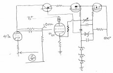
Michael Koster said:OK, to clarify, the 210 and 1100 are stacked for direct coupling. The third supply (60V) is needed to drive the grid positive for class A2 and could be derived from any source e.g. screen grid supply if you had a pentode... BUT arranging it this way provides a direct return path to the cathode, therefore grid current does not have to be dealt with in the current loop of the driver anode or the power tube cathode. The 60V supply in my breadboard amp (common to both channels) consists of a toroid, a bridge rectifier, and a capacitor ;-) Also of note is the 210 and 60 supplies can be shared in a stereo amp because there are no common return current paths to induce crosstalk. Eventually the MOSFETs should probably be cascode for better PSRR but it's very good as it is.
Cheers,
Michael
PS if you trust the isolation of the MOSFET active loads on the outputs, then all the power supplies and filters can be shared in a multichannel amplifier
Yes, I hadn't really focused on the current loops, but having the current loops separated speaks to the thoroughness of the design.
I'm finding, personally, that even with normal resistive or inductive loads, that crosstalk is not a big issue. Yeah, it's there, but to my ears it doesn't degrade the presentation. Good records sound pretty good to me and you're lucky to get 30dB of separation (even then in probably only a narrow frequency range) with a good cartridge.
Sheldon
Wavebourn said:
An infrared LED can be probably used, but it wants about 1.5V, more than your cathode resistor provides.
A common CQY99 IR LED, for which there are probably dozens uppon dozens of equivalents, has a forward drop of 1.25V at 20mA, 1.15V at 10mA, so it should definitely be usable here...
Michael, Sorry , I'm a little slow at this but I'd really like to understand what you're doing . . . . Looking at the Schematic (still) does the current from the 210V loop go through the 60V supply?
I'll try the MosFet in the cathode of the 417 as well as the IR LED (thanks ilimzn!) but I have a question about how generally to choose the part for this use . I don't see what on the data sheet for the 2N7000 indicates it will be good for 12mA @ 2.5VDC (I just grabbed this Grid Voltage from the 417 sheet, not sure if it's accurate in your circuit or not.) A friend told be it would be IDSS but looking at the sheet it doesn't seem to apply with VGD=0vdc. The only thing that looks like it could be it is the "Ohmic Region" chart at the top of page three of the data sheet . Can somebody tell me what to look for?
Wavebourn,
If you have the time and inclination can I ask you to show me how you do this?
Thank you!!
I'll try the MosFet in the cathode of the 417 as well as the IR LED (thanks ilimzn!) but I have a question about how generally to choose the part for this use . I don't see what on the data sheet for the 2N7000 indicates it will be good for 12mA @ 2.5VDC (I just grabbed this Grid Voltage from the 417 sheet, not sure if it's accurate in your circuit or not.) A friend told be it would be IDSS but looking at the sheet it doesn't seem to apply with VGD=0vdc. The only thing that looks like it could be it is the "Ohmic Region" chart at the top of page three of the data sheet . Can somebody tell me what to look for?
Wavebourn,
" There is one more option: to take DC feedback for gyrator from cathode of your output tube coupling tubes directly, but power supply will be more complex. "
If you have the time and inclination can I ask you to show me how you do this?
Thank you!!
Hearinspace said:
Wavebourn,
If you have the time and inclination can I ask you to show me how you do this?
Thank you!!
A first, I would need some negative voltage supply with tiny current requirements, like 1 mA would be enough, so a parametric regulator with one 120V Zener will work fine. You may use some VR tube here, it looks nice indicating power-on as well.
Next, I would make a voltage divider from anode of the driver to that negative rail, so DC in the point between resistors would be zero, to drive the grid of the output stage. Then I would shunt the upper resistor of the divider by existing coupling cap. Now, I would disconnect that resistor in SVCS that goes to anode and senses anode voltage connecting it to the cathode of the output tube. However, it's value would be recalculated for a different voltage.
PS: thanks Ilimzn for the info!
")
Hearinspace said:Hi Wavebourn, Is this what you mean?
Exactly!
Hearinspace said:
I'll try the MosFet in the cathode of the 417 as well as the IR LED (thanks ilimzn!) but I have a question about how generally to choose the part for this use . I don't see what on the data sheet for the 2N7000 indicates it will be good for 12mA @ 2.5VDC (I just grabbed this Grid Voltage from the 417 sheet, not sure if it's accurate in your circuit or not.) A friend told be it would be IDSS but looking at the sheet it doesn't seem to apply with VGD=0vdc. The only thing that looks like it could be it is the "Ohmic Region" chart at the top of page three of the data sheet . Can somebody tell me what to look for?
The "Transfer Characteristics" chart to the right of the Ohmic region chart is a good first approximation. Looing at the graph, one would expect temperature sensitivity and drift but I find the circuit is much more stable than I would have guessed. It is about 2.5 -2.6 volts at 10-12 mA. The dynamic resistance is about 10 ohms at this current, similar to an LED.
"does the current from the 210V loop go through the 60V supply?"
The current through the MOSFET has two branches, one through the 417A anode which returns to ground and the other through the 801A grid which returns to the 801A cathode. The standing anode current of the driver and the driver's share of grid current, which is Ig/(gm*R1), is supplied by both 60V and 210V supplies, and the remainder of the grid current is supplied by only the 60V supply.
Michael
But this is still cap coupled isn't it?Wavebourn said:Exactly!
. . . . .Ahhh, what do I know. I'll still try it.
I'll play around with the present SVCS and the cathode loads for a week or so and then try the direct coupled version. Thanks Wavebourn !
By the way, can I just swap an N channel Mosfet for the PNP in the SVCS?
Michael Koster said:
The "Transfer Characteristics" chart to the right of the Ohmic region chart is a good first approximation. Looing at the graph, one would expect temperature sensitivity and drift but I find the circuit is much more stable than I would have guessed. It is about 2.5 -2.6 volts at 10-12 mA. The dynamic resistance is about 10 ohms at this current, similar to an LED.
"does the current from the 210V loop go through the 60V supply?"
The current through the MOSFET has two branches, one through the 417A anode which returns to ground and the other through the 801A grid which returns to the 801A cathode. The standing anode current of the driver and the driver's share of grid current, which is Ig/(gm*R1), is supplied by both 60V and 210V supplies, and the remainder of the grid current is supplied by only the 60V supply.
Michael
Thanks Michael, I wondered about the grid current . But as far as the power supplies go, the diagram makes it look like current from the 210V loop might also have to go through the 60V supply and if so I'm wondering how that happens. Am I wrong about that?
Hearinspace said:
But this is still cap coupled isn't it?
It is DC coupled, but cap shunted.
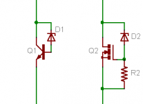
By the way, can I just swap an N channel Mosfet for the PNP in the SVCS?
You can swap, but you should consider base currents, that means resistors should have smaller values, but the capacitor should have higher value.
Wavebourn said:
You can swap, but you should consider base currents, that means resistors should have smaller values, but the capacitor should have higher value.
Oops... I did not understand your question, I was thinking about swapping of P-type mosfet by PNP transistor, because in microphone preamps I used exactly PNP transistors, before found source of suitable P-type MOSFETs.
No, you can;t. But you can use NPN transistor instead of N-type MOSFET, Base-emitter breakdown voltage is about 5 times less than gate-source bias for given current, so adjustment will be needed. Also, BJT have a secondary breakdown due to uneven base width.
Hearinspace said:Thanks Michael, I wondered about the grid current . But as far as the power supplies go, the diagram makes it look like current from the 210V loop might also have to go through the 60V supply and if so I'm wondering how that happens. Am I wrong about that?
I suggest printing out the schematic, and completing the loops visually. It's easier to see that way. Remember, all the current from one end of a loop, has to return to the other end. The current from the 210V supply has to return to common. The only way it can do that is through the driver tube. So yes, it has to go through the 60V supply too. But the 60V supply also supplies grid current to the output tube. This current does not return the common, but to the top of the 210V supply, where it returns to the 60V supply. So all of the 210 supply current goes through the 60V supply. But not all of the 60V supply current goes through the 210V supply, some of it circulates is a separate closed loop.
Sheldon
Thanks Sheldon. My question is a very simple one and isn't really about the amplifier circuit per se. It's two pronged, first it's that I've never seen current from one supply run through the rectifier of another and wanted to make sure that that was really what was happening before I filed it away in my mind as a workable option. And then I also wondered (if that is the case) doesn't the less filtered 60V supply add noise to the previously filtered 210V current? None of this is meant to be critical or judgmental in any way. I'm just trying to learn.
Wavebourn said:Oops... I did not understand your question, I was thinking about swapping of P-type mosfet by PNP transistor, . . . .
Actually, you DID understand my question - I just asked it wrong.
Hearinspace said:Thanks Sheldon. My question is a very simple one and isn't really about the amplifier circuit per se. It's two pronged, first it's that I've never seen current from one supply run through the rectifier of another and wanted to make sure that that was really what was happening before I filed it away in my mind as a workable option. And then I also wondered (if that is the case) doesn't the less filtered 60V supply add noise to the previously filtered 210V current? None of this is meant to be critical or judgmental in any way. I'm just trying to learn.
Yes, the current trough the input tube is in series, so has to go through the series path of the supply. Unusual for us, but not really exotic, if you think about it. Turn the 60V supply off - just the secondary, diodes, and any other series resistance in the path.
Hadn't thought about the second part of the question. Interesting. I guess that it would add a little ripple, but not the full ripple amount of the 60V supply. Since they are in series, the two supplies form a divider, so t would depend on the output impedance of the 210V supply, as to how much the ripple in the 60V supply would modulate the voltage on the 210V node. Shouldn't be hard to design for low ripple there. A low impedance supply at 120Hz would have current ripple at that node, but not voltage ripple. Curious as to Michael's take.
Sheldon
Hearinspace said:Thanks Sheldon. My question is a very simple one and isn't really about the amplifier circuit per se. It's two pronged, first it's that I've never seen current from one supply run through the rectifier of another and wanted to make sure that that was really what was happening before I filed it away in my mind as a workable option. And then I also wondered (if that is the case) doesn't the less filtered 60V supply add noise to the previously filtered 210V current? None of this is meant to be critical or judgmental in any way. I'm just trying to learn.
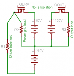
It's a little tricky to get one's head around, I admit. Here's how I think about the current loops. The driver load goes across the 60V and 210V in series. The current through both is the same because they're in series. They are both supplying power to the driver load. The power grid loop is separate as shown. Noise in both loops is isloated by the MOSFET, and the 2 loops are isolated from each other by the bootstrapped MOSFET source resistor (not shown here). The 210V supply needs to be clean to avoid coupling noise through the internal resistance of the driver tube referenced to the power tube cathode.
There are some shortcuts in this circuit because it's on a breadboard. For example, I would prefer the bias referenced to the power tube cathode rather than ground, but this is convenient for testing.
Cheers,
Michael
PS I worry about a short from the top of the 1100V supply to ground so I add a big reverse biased diode across the 210V supply.
Attachments
ilimzn said:
A common CQY99 IR LED, for which there are probably dozens uppon dozens of equivalents, has a forward drop of 1.25V at 20mA, 1.15V at 10mA, so it should definitely be usable here...
Are there devices like this and the MOSFET (in the way Michael used it on the 417A) that can be used for larger currents and voltages? I'm thinking specifically of the VT-25 cathode - very roughly 30VDC/28mA. I looked for both IR diodes and MOSFETS last night and didn't find any but there are thousands of models and I could have missed them.
Hearinspace said:
Are there devices like this and the MOSFET (in the way Michael used it on the 417A) that can be used for larger currents and voltages? I'm thinking specifically of the VT-25 cathode - very roughly 30VDC/28mA. I looked for both IR diodes and MOSFETS last night and didn't find any but there are thousands of models and I could have missed them.
They have cut-off voltages below 4V. Try 27V Zener with 100 Ohm resistor in series.
Hearinspace said:
Are there devices like this and the MOSFET (in the way Michael used it on the 417A) that can be used for larger currents and voltages? I'm thinking specifically of the VT-25 cathode - very roughly 30VDC/28mA. I looked for both IR diodes and MOSFETS last night and didn't find any but there are thousands of models and I could have missed them.
I wonder if something like this would work?
Attachments
- Status
- This old topic is closed. If you want to reopen this topic, contact a moderator using the "Report Post" button.
- Home
- Amplifiers
- Tubes / Valves
- Gyrator Question