I wired up a gyrator and put in my 40v supply, it ended up with 4 volts at the output, I assume I miss wired it, however just to be sure I'm going to ask a quick question. I used this schematic
http://www.loetstelle.net/projekte/gyrator/gyrator.php
Do I hook this up between B+ and ground, or along the B+ rail like a normal choke?
http://www.loetstelle.net/projekte/gyrator/gyrator.php
Do I hook this up between B+ and ground, or along the B+ rail like a normal choke?
Not speaking Dutch my guess is it's an in-line device. It's polarity sensitive so you gotta connect it the right way X1-1 to the +ve rail X1-2 to the load.
Also. it needs a current through it to work. Were you testing open circuit?
As you pull current through it, the cap charges up and "programs" the current source Q1-R3. The MOSFET regulates it's Rds to maintain said current.
Also. it needs a current through it to work. Were you testing open circuit?
As you pull current through it, the cap charges up and "programs" the current source Q1-R3. The MOSFET regulates it's Rds to maintain said current.
Right. And a voltage drop on it will be about 5V plus voltage drop on the resistor in source.
There was a thread recently about gyrators.
Here it is: http://www.diyaudio.com/forums/showthread.php?postid=1778215#post1778215
There was a thread recently about gyrators.
Here it is: http://www.diyaudio.com/forums/showthread.php?postid=1778215#post1778215
")
Hi Wavebourn,There was a thread recently about gyrators.
Why does the term Gyrator apply to your circuit? It's your original idea, why not give it an original name?
Thanks
I tried to build that gyrator myself and promptly smoked it. I haven't tried to repair it yet, but I believe my mistake was to work exclusively from the schematic. I'd suggest using the PCB layout as a wiring guide.
My test was done on a 300v +180ma circuit. Indeed X1-1 in your "In" and X1-2 is your "Out". The next test I'll do will be on a lower voltage/current circuit with a resistor load. Won't get a chance to play until after I get into my next house.
Pictures? I'm curious how you've done yours.
My test was done on a 300v +180ma circuit. Indeed X1-1 in your "In" and X1-2 is your "Out". The next test I'll do will be on a lower voltage/current circuit with a resistor load. Won't get a chance to play until after I get into my next house.
Pictures? I'm curious how you've done yours.
I have seen someone else complaining about the circuit, in that it oscillated wildly...maybe that also happened to Whitelabrat's circuit?
I have made a layout to build this unit on protoboard, but was not able to put it together, yet. I included space for a small resistor (couple R) in series with the drain as well as space for a gate stopper resistor (around 1k). I think that at least the gate-stopper is very important!
Let's see if I can put it together in the weekend and test it.
Hearinspace said:
Hi Wavebourn,
Why does the term Gyrator apply to your circuit? It's your original idea, why not give it an original name?
Thanks
Thanks;
I don't invent a terminology usually. But I have to think about it, thank you!
Ok, well that solves that problem. Taking the gyrator out solved the problem of the distortion, mostly. My tube section is running about 25v hot and the mosfets are about 16v hot. So I need to go back in and increase the resistors in my RC sections. Hopefully that will bring the distortion down even further. However, even through the minor distortion thats still left I can tell this amp is going to kick my Kt-88 amp in terms of bass response.
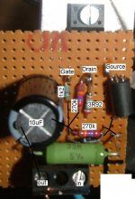
Yesterday I put the gyrator together. I used a IRFBC30... which has an insulated TO220 'body'. I am using a 4R resistor in series with the drain, a 1k2 gate stopper and a ferrite bead in series with the sources (all measures to decrease chance of oscillation). The cap employed is a 10uF one...
I works and it makes the supply quiet! I tested it in a small PP amp that was running with a standard choke. With 200mA through the gyrator, it was dropping 16V. Just for comparison I replaced it with a 80R resistor (80R x 200mA also drops 16V) and the hum was audible. So indeed, it works and filters some ripple away...
I works and it makes the supply quiet! I tested it in a small PP amp that was running with a standard choke. With 200mA through the gyrator, it was dropping 16V. Just for comparison I replaced it with a 80R resistor (80R x 200mA also drops 16V) and the hum was audible. So indeed, it works and filters some ripple away...
Did you follow the schematic or the lay out you get when you click on the picture at the bottom? I remade mine using the lower layout. I was really tired when I posted my last observation and since found that my RC sections were way off and that my mosfets were only getting 4v not the 50 something I thought they were. So I fixed that problem and I hooked my Gyrator back up and burnt out R3.... So I upped the wattage of R3, I'm going back to the split rail to lessen the load, made 2 gyrators and am going to try it again. I'll report back...
R3 should indeed be relatively large... in my case (with 200mA draw by the amp) it burns around 1,5W. I used a 3W MOX unit...
I followed the schematic, and layed components so that distances were minimized. I took a picture, attached, with values. The picture is crap, but you get the idea about the layout. The black traces indicate how components are connected together, under the board.
One thing to reconsider is the positioning of the 10uF cap... it will get quite hot from the 33R resistor...
I hope this helps, but feel free to ask!
Attachments
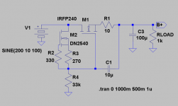
I'm trying to understand the purpose of R1 and C1 providing a high
AC impedance when that circuit node has a 100uF cap to AC ground.
What happens if R1 and C1 (and C3 for that matter) are removed?
I think if this were on a PCB and had 2 or 3 different connections to
R1, it could be built as a screen regulator, a high impedance fixed
voltage anode load, mu-follower, anti-triode, etc. It's a nice set
of functions to have in one place..
On a related note, I'm looking at a DC filament gyrator as an
alternative to filament chokes or VCCS. The circuit looks similar
to yours but without C3. It would provide fixed voltage (on a
controlled ramp) and present a (relatively) high AC impedance
to the signal current on the filament.
Cheers,
Michael
- Status
- This old topic is closed. If you want to reopen this topic, contact a moderator using the "Report Post" button.
- Home
- Amplifiers
- Tubes / Valves
- Gyrator Question