Thank you Peter;
though they appear to be large, I don't think they will be happy on 1A current. I have in mind a MOSFET current mirror with relatively high ratio (cascoded, actually): I am going to finish my Festival powered speakers I postponed to design as desired the last year (hybrid, class A+C+C).
I will rather use some Toshiba devices bolted together...
Does it need to be a "Mirror", where one current is slave to
the other? Or just two current sources that exactly match?
If only matching is the concern: Alephs share some of the
same benefits as cascodes. Collectors move in response
to error correction as needed. But the control transistors
never directly see what swings at the drains. Early effect
is present, but has no influence over regulated currents.
Collectors are not in the path of the regulated current.
Never any need for matched bipolars to pull a full Ampre
in the circuit described above. Though MOSFETs involved
may easily exceed that figure.
On the other hand: If you need a mirror to copy or multiply
an arbitrary variable current to the other channel, I havn't
figured how one could do that with Alephs yet.
kenpeter said:Does it need to be a "Mirror", where one current is slave to
the other? Or just two current sources that exactly match?
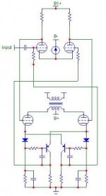
That was the gist of my question a few posts back. We are talking about tubes. I assumed that the goal was to balance DC in the output transformer. The original post suggested use of a single thermaltrak device, and resistors. If that works well, this device is robust enough and the application appears uncomplicated. Then discussion started on various ways to improve it, until we are talking about more complex systems that don't involve the original idea.
So what is the goal here? What problem are we trying to solve. I feel like I'm missing an important point somewhere (wouldn't be the first time).
Sheldon
edit: How closely matched to they have to be? I can't imagine it's that difficult to get well within a percent or so.
kenpeter said:Does it need to be a "Mirror", where one current is slave to
the other? Or just two current sources that exactly match?
It needs to be a mirror with current ratio about 10 and high output dynamic resistance.
So what is the goal here? What problem are we trying to solve. I feel like I'm missing an important point somewhere
You were right. DC current matching.
How closely matched to they have to be? I can't imagine it's that difficult to get well within a percent or so.
I don't think it has to be extremely precise. Figure that the OPT is not perfectly symmetric and the current mirror is only handling DC. This is why I prefer to keep it simple.
Jeb-D. said:Thanks Jan.
The part I'm trying is ON-Semi NJL3281D. The data sheet didn't really have any info regarding the diode section. I'll just breadboard it up when the samples arrive. If it doesn't work out, I'll just use the parts for a different project.
OK. The On-semi's don't have a specific spec of at what current they track IIRC so you need to find that out yourself. I'd be interested in your results. Keep us posted!
Jan Didden
Speaking of current sources in cathodes, do they really need to track each other?
What if to make them as current mirrors that reflect the current set by a trimpot from a voltage source?
By the way, does anybody know of transistor pairs thermally tracking each other, in which one of transistors can work on 1A before the beta droop region?
I need much more precision current mirroring that diode+transistor pairs allow.
Well, the samples arrived yesterday. There is defiantly a voltage drop difference between the diode and the BE junction of the transistor per given current. I love how the datasheet really explains nothing about the relationship between the diode and BE junction of the transistor.
Steady state measurements (I do not have to tools to do test for temperature tracking). It's looking like if I use degeneration resistor values that allow for a 1V drop, it will give 3% imbalance in current (which is 1.8mA in this particular circuit). Degeneration resistors that allow for a 2V drop give a 1.5% imbalance (which is .9mA in this particular circuit).
I'd consider the above usable for this app, but wonder if a standard 2 device mirror would be much more accurate. It would for sure, if both devices were the same temp, but since there will be thermal resistance between the two. I am just wondering if the temperature mis-match in a 2 device configuration would cause a similar current imbalance to the thermaltrak configuration.
Perhaps shrinking the bias resistor and going with some rather large degeneration resistors (that drop like 1/2 the bias voltage) would provide good match. Though in this case, voltage drop across the silicone wouldn't matter much at all. Resistor tolerance would be the primary cause of imbalance. A 1n4007 paired with some random power NPN could probably do the job accurately.
I can see any problems using this solution. Add 15ohm under the diode and a 20ohm pot under the emitter to trim fo equal currents through both tubes. This only needs to be done once and for all. As I showed earlier in our SEPTOR it works like a charm IRL. Used two BD139s in that one.
I can see any problems using this solution. Add 15ohm under the diode and a 20ohm pot under the emitter to trim fo equal currents through both tubes. This only needs to be done once and for all. As I showed earlier in our SEPTOR it works like a charm IRL.
I had thought about that. But, was thinking. You set the currents equal by using unequal resistances. Now what happens if say, the operating temperature changes (or ambient), which causes both BE junction V drops to change by and equal amount. It will cause an un-equal current change between the two. Though I'm sure in most practical cases, the imbalance caused would be very small.
Do not worry Jeb! Tracking will stay within 1mA from 25 to 90 degrees C when resistors are 15 to 12ohms. A realistic temp diff would be 30 degrees at most.
Even if you use a mainstoroid for OPT you will have an open window of at least 5mA.
Even if the Thermaltrack solution looks nice, it seems like a waste of money as two dirtcheap BD139s at the same heatsink probably will do the job better.
Even if you use a mainstoroid for OPT you will have an open window of at least 5mA.
Even if the Thermaltrack solution looks nice, it seems like a waste of money as two dirtcheap BD139s at the same heatsink probably will do the job better.
tomchr said:
It looks interesting Tom,
http://www.datasheetcatalog.org/datasheet/diodes/ds30436.pdf
but I bought already few hundreds of 2SC1815 from Toshiba.
Even if the Thermaltrack solution looks nice, it seems like a waste of money as two dirtcheap BD139s at the same heatsink probably will do the job better.
That's pretty much what the testing I did yesterday indicated. The voltage drop difference between the diode and B-E of the BJT was larger than the difference between the B-E's of different transistors.
It is close enough to work decent, but the diode and BJT were obviously optimized for different quiescent currents. This kind of throws out any advantages the Thermaltrak may have had for this application.
Unfortunately, the Thermaltrak idea is one that doesn't seem worth pursuing at this point. If the diode were identical to the B-E portion of the BJT, it would be. But, being that they aren't, I'm probably going to use a pair of cheap NPN's as you suggest.
- Status
- This old topic is closed. If you want to reopen this topic, contact a moderator using the "Report Post" button.
- Home
- Amplifiers
- Tubes / Valves
- ThermalTrak transistor application.