I started laying out a PC board for my "universal driver" design while I was sitting around a hospital in Pittsburgh waiting for my mother in law's chemo treatments (late December).
I finished the lay out in a hotel room in Georgia on my trip home (December29).
I made two "home cooked" PC boards right before I had to go back to work in January.
I started populating one board in early January. Then Sherri had to go back up north, tasks started piling up, my job started demanding long hours, so the board sat on the shelf unfinished.
Today was the first day that I have had a few hours of spare time this year, so I got the unfinished board off of the shelf and started soldering.
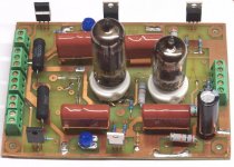
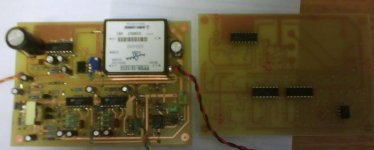
I put all of the parts necessary for testing on the board. Everything looked OK so I hooked it up. Nothing, NADA, zip, not even heater glow. I had 6.5 volts right on the pins of the tubes, but nothing. This sickening feeling came over me. When I realized what had happened, I strongly resisted the temptation to throw the board into the trash, or worse!
Back when I made the board, I had swapped the top and bottom transparencies. The board is a mirror image of what it is supposed to be. Which brings me to one of the first rules of laying out a PC board. ALWAYS put some text on the board somewhere on EACH layer. I was in a hurry when I laid out this board, so I left the text off. Text would have made it obvious that the board was mirrored.
So now I can toss the board in the trash, nuke it in the microwave, run it over with the truck, or try to salvage it. If I had to choose right now I would nuke it, but that really stinks up the house, so I cracked open a Bud Light instead. I may have some time to deal with it tomorrow. It may be possible to remove the tube sockets and semiconductors and put them on the back side of the board.
I have about 10 days until I must travel back to West Virginia to help with Sherri's mother. I will be gone for about 10 days which will put me behind again, so tube time will be limited. On the bright side if I time it right, I might get a day or two to hit the Dayton Hamfest. It is the biggest electronics flea market in the world (or so they say).
I finished the lay out in a hotel room in Georgia on my trip home (December29).
I made two "home cooked" PC boards right before I had to go back to work in January.
I started populating one board in early January. Then Sherri had to go back up north, tasks started piling up, my job started demanding long hours, so the board sat on the shelf unfinished.
Today was the first day that I have had a few hours of spare time this year, so I got the unfinished board off of the shelf and started soldering.
I put all of the parts necessary for testing on the board. Everything looked OK so I hooked it up. Nothing, NADA, zip, not even heater glow. I had 6.5 volts right on the pins of the tubes, but nothing. This sickening feeling came over me. When I realized what had happened, I strongly resisted the temptation to throw the board into the trash, or worse!
Back when I made the board, I had swapped the top and bottom transparencies. The board is a mirror image of what it is supposed to be. Which brings me to one of the first rules of laying out a PC board. ALWAYS put some text on the board somewhere on EACH layer. I was in a hurry when I laid out this board, so I left the text off. Text would have made it obvious that the board was mirrored.
So now I can toss the board in the trash, nuke it in the microwave, run it over with the truck, or try to salvage it. If I had to choose right now I would nuke it, but that really stinks up the house, so I cracked open a Bud Light instead. I may have some time to deal with it tomorrow. It may be possible to remove the tube sockets and semiconductors and put them on the back side of the board.
I have about 10 days until I must travel back to West Virginia to help with Sherri's mother. I will be gone for about 10 days which will put me behind again, so tube time will be limited. On the bright side if I time it right, I might get a day or two to hit the Dayton Hamfest. It is the biggest electronics flea market in the world (or so they say).
Attachments
On the upside:
1. You only populated one board.
2. You cooked them at home, so even if you destroy one, you're not out 75-100 bucks for someone else to proto the board for you.
3. You get to go to a big Hamfest. I've never been to one, not even a small one.
Don't get too frustrated. I'm pretty sure everyone that knows you realizes that you're dealing with a family illness, and that they need your support.
Jeff
I've had a few bad days, too. I used to lay out boards using rub-on resist pads and rub-a-dub marker (it works if the PCB copper is 1 oz or thinner - otherwise you get pinholes). I went all the way through the process of laying out and etching the board (a hybrid amp using the UA739 IC), then realized everything was mirror imaged. Duh...
Hey, don't worry - we've all done it.
I've laid out 100's of boards always at 2x or 4x full size and always put two accurate dimension lines with "reduce to [whatever dimension]" on the film. One day I got back a very odd sized PCB from our manufacturer - I put the wrong size on the film. Good job it was a prototype and not a production run!
I've laid out 100's of boards always at 2x or 4x full size and always put two accurate dimension lines with "reduce to [whatever dimension]" on the film. One day I got back a very odd sized PCB from our manufacturer - I put the wrong size on the film. Good job it was a prototype and not a production run!
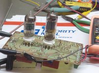
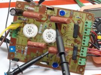
Last night I was rather disapointed by my stupidity and almost tossed the board. Today I had to prepare our 8 year old vehicle for a 2500 mile trip. While I was underneath the car I was thinking about the board and two blonde brain cells must have got together and ignited a spark. I didn't need to rip the board apart, I didn't even need to take the tube sockets out. I could just tack solder two more sockets on the back of the board. The CCS chips have 3 pins. The center one is the input and the other two are tied together through two resistors. I just need to swap the two resistors. All of the other parts have two leads, they don't care which side of the board they are on. I left the car half finished and came inside to try this out.
Attachments

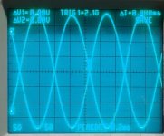
Does it work? There is no PowerDrive circuit yet (those parts might wind up on a piece of perf board due to another really blonde idea), but does 400V peak to peak of drive from a 550 volt supply sound like enough to make some screen grids glow?
I reduced the input level to make the picture fit the scope screen. This picture is only 350 volts peak to peak. Now I must go outside and put some oil in the car engine before I do something else really dumb!
I reduced the input level to make the picture fit the scope screen. This picture is only 350 volts peak to peak. Now I must go outside and put some oil in the car engine before I do something else really dumb!
Attachments
I was mounting transformers in a box for the 833 project, i needed a hole in the base plate of the transformer, so i brought out the drill and started drilling very carefully to make sure i wouldent jam the bit into the primary, what happens ?
I jam the stupid bit right into the primary of the main power transformer, during a first visual inspecion i feared the worst so i had to test it to make sure it really was dead, it was a big relief hearing the startup hum, turns out i reacted fast enuf and only scratched the surface of the wire.
In the end the transformer ended up in a different location and needed yet another hole in the base plate, luckily this time the hole got drilled without any damage.
Anuther flunky was when drilling the mounting holes for another transformer, mistaking a scratch for an actual drill mark*DOH*
So often, Murphy prevails
Well I finished the car so I resumed where I left off. I had previously twisted my power supply as far as it would go to see how much drive voltage this thing could put out. The power supply goes to 550 volts. While working on the car I was thinking 550V? The 10M45 is only rated for 450 V why didn't it blow? When I resumed I was scoping the 10M45 and I discovered that it was indeed seeing about 500 volts. It was also starting to smoke! Power OFF! Well the 10M45 will indeed handle 500 volts, It really does not like to dissipate nearly 5 watts without a heat sink. Heat sink added. Heat sink is elevated to 550 volts. Note to self. Don't touch it. While doing some further testing I started to smell a smell that only an electrolytic cap can make. Note to self, 400 Volt caps really don't like 550 volts. I took it out. Board works fine without it. It ran for 1/2 hour at 550 volts.
I have decided to cease playing with this dangerous toy. I have tempted Murphy twice already and I don't want to have him visit me today. I want to add the PowerDrive circuit so that I can make something glow. This means moving the CCS's to the other side of the board. If I get done tonight I will "test" some tubes. I don't know which ones yet.
You were really tempting the old gentleman. You must have an angel hovering over your head these days... Murphy has visited me at times in the past few weeks - usually his malice is confined to shocks from charged caps or fractured surface mount caps that are impossible to diagnose (shotgun the lot and pray). I have my own driver that I'll be testing in the next couple of months, as soon as I get some musical and job obligations out of the way. Our goals are the same - drive the heck out of some screens and have some juice left over for NFB.
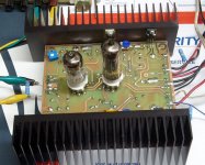
Yes< this little project started out on shakey ground, stumbled a few times, but grew up big and strong. I moved some more parts from one side of the board to the other, and added the mosfets. I installed some absolutely monstrous heat sinks because they happened to already have tapped holes in the right places.
I plan to use this WMD to find the limits of screen drive, but first I intend to answer a question that I have wondered about since I was about 15, but only now have the ability to really answer. The question? Just how many watts can a pair of 6L6GC's put out without melting?
I have made guitar amps since I was 14. Most of my early ones used old TV parts, but somewhere in High School I graduated to 6L6GC's. My best amps strained to make 60 watts. I know that a major weak point is the propensity for an arc to occur between pin 3 (plate) and pin 2 (heater). This limits the plate voltage, so I plan to explore the possible power gains to be had by using AB2.
I will report on these activities in the 6L6GC AB2 Amp thread and the Screen Drive Push Pull ideas thread.
Attachments
Bad days, these are getting ever more common. Recently I purchased some USB digi scope software and after loading the stuff in my laptop; later found this "new thingy" didn't work and repeatedly crashes into desktop. One goes through the reload and download updates. Claimed for XP working I gotton on to the manu and after a downtime bank holiday they were aloss to find a solution. What really annoys me, is the time I spend degugging someone elses flawed b-astard software to find no comments have been added behind software routines. Such glossy product writeup's and performance prowesses but beware of such flawed software and crappy customer service. Again reorganising return of goods and cash back is another irritating lark some of us experience. At least the replacement of duff tubes is largely quibble free.
My black cat persuaded me to find the problem. It was simple. The product uses 5V USB port. I discovered the juice dropped to 4V when certain digiscope functions were started. So I spliced another cable to the 5V and it now works. Why the hell do manufacturers design equipment on the borderline 0.5A current from a USB port ? This is an accepted standard. What is the next shortsightedness.
richy
- Status
- This old topic is closed. If you want to reopen this topic, contact a moderator using the "Report Post" button.
- Home
- Amplifiers
- Tubes / Valves
- You know that you are having a bad day when.......