Dear All,
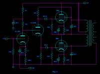
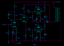
I found a SEPP circuit from an old magazine of year 1966 as Fig-1 shown. It was using an output transformer which has two groups of primary windings. Can anybody explain what is the different if using a single winding transformer as Fig-2 and the advantages and disadvantages in comparison?
Thanks
Patrick
Attachments
Hi Patrick,
Not any more than I have really... I haven't studied or explored parafeed transformers that much, outside of making a pair for a headphone amp that used neither of these topologies. So I shall derfer to someone who may know more.
Cheers!
pat49hk said:Dear Geek,
Thank you for your response. Can you tell me more details of the transformer winding topology of both?
Not any more than I have really... I haven't studied or explored parafeed transformers that much, outside of making a pair for a headphone amp that used neither of these topologies. So I shall derfer to someone who may know more.
Cheers!
Hi Patrick !
I did a similar project.
Here are some pics about it.
regards, Simon
I did a similar project.
An externally hosted image should be here but it was not working when we last tested it.
Here are some pics about it.
regards, Simon
pat49hk said:Dear All,
I found a SEPP circuit from an old magazine of year 1966 as Fig-1 shown. It was using an output transformer which has two groups of primary windings. Can anybody explain what is the different if using a single winding transformer as Fig-2 and the advantages and disadvantages in comparison?
Hi,
Fig1 is right for pentodes fig 2 is only work for triode.the two resistor of g2 will eat most of the output power.
Cheers!
Singh
Shoog said:That parafeed cap seems very small. When i messed about with parafeed I always used something around 4uf.
68uF<4uF?
I found and am intrigued by this circuit in a signal generator's amp section. It's a SEPP circuit with output transformer. My questions: is the output transformer working in PP operation with the benefit of canceling distortion just like a traditional PP circuit, given that it has DC blocking capacitors or is it just a fancy way of doing parallel feed single ended? What's the benefit of doing this way? What kind of requirements for the output transformers other than split primaries?
I also added polarity markers to all the junctions in the simplified schematic to better understand its operation. I hope that helps.

I also added polarity markers to all the junctions in the simplified schematic to better understand its operation. I hope that helps.
Pat49hk.
Intriguing!
That reminds me of an early VSAC in Silverdale Washington (Vacuum State of the Art Conference).
One of the commercial rooms was showing off an amplifier with an unusual SRPP output stage.
if I remember correctly, the output stage's top tube was a 300B, and the bottom tube was a KT66.
It might even have DC coupled the 300B to the KT66 through a low Ohms resistor, with only a single capacitor to couple to a single winding primary of a non-air gapped output transformer.
Like Post # 2 (Figure 2)?
Does anybody remember that amplifier?
. . . I wish I could find some documentation on it.
Thanks!
I was in Hong Kong in 1968, 1969, 1973, and 1974. Quite a nice city and the mainland territory too.
Those were good days.
For audio power SEPP amplifier look at the Philips AG9015 ... normally those 2 windings are just for G2 supply and there is a third winding from middle point to ground coupled by an electrolytic cap used as primary . Or OTL 800ohm without using the transformer .
This is because without independent floating G2 voltage for the upper tube ( too expensive in those days using tube rectifiers ) you need the winding inductive reactance in series with G2 , just using low-ish resistors would short the output power to ground / B+ .
And using high value resistors would greatly limit the power ( they did this in TVs and radios just 2-3W from 2 tubes) .
For low power , like in the generator schematic , probably the 2 windings can be used also as primary , but only if you use one winding for both tubes the Raa is reduced by 4 - the advantage of SEPP
So if you use modern floating power supply for G2 , or with triodes , you don't need the two windings , you use a simple like SE transformer but without air gap of course . .
Last edited:

- Home
- Amplifiers
- Tubes / Valves
- SEPP output transformer