hey-Hey!!!,
If you need low output Z, you'll need low plate loads. To get gain, you'll need gm...so back to the EL84 pair, 8k plate loads, g2 of ~100V or so. Similar stuff available with 829/832...")
I am just using dual 6AC7 in my most recent builds. Very nice results and the internal screen and supressor each have their own pin.
cheers,
Douglas
If you need low output Z, you'll need low plate loads. To get gain, you'll need gm...so back to the EL84 pair, 8k plate loads, g2 of ~100V or so. Similar stuff available with 829/832...
I am just using dual 6AC7 in my most recent builds. Very nice results and the internal screen and supressor each have their own pin.
cheers,
Douglas
Bandersnatch said:hey-Hey!!!,
If you need low output Z, you'll need low plate loads. To get gain, you'll need gm...so back to the EL84 pair, 8k plate loads, g2 of ~100V or so. Similar stuff available with 829/832...
The same here.
I use 17K resistors in anodes and 120v on screens
Though, plate load resistance is lower because of parallel feedback from output tubes, it's exactly about 8K.
Also, Jeb-D; what you've discribed is a positive feedback by voltage. It helps to get more watts from toobs, but increases output resistance.
If I implement the Mosfet on top (Constant Voltage Element in a Super Linear Cathode Follower) then the plate will have signal to tap off and be available to the screens.
Since I will be running the 6080's at high current (100mA) the amount of gain I will need from the front end is very modest and the pentodes should have more than enough even when screen feedback is taken into account.
Jed your idea plan is different to what i has in mind - but definately an option. That little bit extra output watts might just be worth it. Also thanks for the hint about screen resistor - ala Baby Huey.
All in all this shaping up to be an interesting, and potentially nice sounding design. I will throw together a concept drawing over the next few days.
Shoog
Also, Jeb-D; what you've discribed is a positive feedback by voltage. It helps to get more watts from toobs, but increases output resistance.
If your referring to the cross-couple screen feedback, you are mis-understanding.
For common cathode output; screen feedback should be cross-coupled.
For cathode follower output; screen feedback should be locally coupled.
I will throw together a concept drawing over the next few days.
Got a little eager did we
I'm not too familiar with the trick you are implementing with the mosfets. How much voltage(AC) are you anticipating on the plates?
For common cathode output; screen feedback should be cross-coupled. For cathode follower output; screen feedback should be locally coupled.
I meant traditionally. Cross-coupled should work for the above cathode follower.
The CCS will need about 30V if memory serves, and the transformer has a few ohms resistance..
The 6080's will need a 100V.
The MOSFET will need another 30V.
So the 6080 will have just 130V on the plate, for a +B of 160V.
The MOSFET is there to push against the rising plate, it effectively keeps the triode with a constant voltage, and with the CCS, a constant current over it - which keeps it in exactly the same operating point at all times - and hence Super Linear.
Shoog
+B of 160V
You should be able to get a pretty clean 60Vpp from the 6bn11 with that. Using a plate resistor less than, or equal to 10k.
I can give some recommendations if you don't already have something in mind.
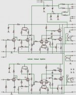
I am offering up a few suggestions based upon a SE version and P-P simulations only. I have not yet built a push pull SLCF amp yet. I do have a SE "augmented cathode follower" amp running and the principles outlined below were found the hard way. The schematic to that amp is included. The B+ was 300 volts and the negative supply was -250 volts.
1) The cathodes of the output tubes will need to move up and down with the output signal which will be large, depending on the desired load impedance and power output. The CCS's are returned to ground which prevents the cathodes from going below ground potential. I have found the need to connect the CCS's to a negative voltage source. Based on simulation only.
2) The cathodes will go up too. To keep the voltage at a constant 100 volts across the 6080 the plate must be able to move up too. This means more than 30 volts across the mosfet AT IDLE. You will need 30 volts plus half of the expected peak to peak output voltage. Proven on the SE version which used a tube so I ran about 150 volts across each device at idle. This was to keep the dissipation in each half of the tube similar. It is not necessary or desired with a mosfet on top.
3) The CCS in the output circuit will have a very high AC impedance. Ideally infinity, in practice 100K ohms is common for a 100 mA source. It is in series with your OPT. Most of your output voltage will be across the CCS with very little in the OPT. The solution, hang the OPT between the two cathodes. A single winding OPT will work, or the CT can be ignored. There should be no DC through the OPT, so just about anything should work. Based on simulation only.
4) A simpler solution that does not use a CCS is to use an ordinary P-P OPT with the center tap grounded and the "plate" leads connected to each cathode. This does not force a true constant current at DC but the OPT's inductance provides a pseudo constant AC current and allows the cathode to swing below ground. Technique used on SE version (with 600 ohm SE OPT).
I now have a power supply big enough to find the SE versions true potential, but have not had the time to experiment yet.
Attachments
Jeb-D. said:
If your referring to the cross-couple screen feedback, you are mis-understanding.
For common cathode output; screen feedback should be cross-coupled.
For cathode follower output; screen feedback should be locally coupled.
...and in both cases it will be a positive feedback. However, being an Electronics Engineer, I may be not familiar with some amateur terminology that may use common word to describe something opposite...
Mmm. I'm starting to wonder if that input stage is going to behave weird with balanced feedback. Since V3 is dependent on V2 (electrically 1 stage after).
Perhaps it will work ok. If it's problematic, you can use an input transformer to split the phase, or remove the feedback and go a different route.
Just a thought.
Perhaps it will work ok. If it's problematic, you can use an input transformer to split the phase, or remove the feedback and go a different route.
Just a thought.
being an Electronics Engineer, I may be not familiar with some amateur terminology
Did you try looking up "cross coupled feedback" before deciding it was amateur terminology?
...and in both cases it will be a positive feedback.
I can see your case once the amp crosses over into class B. But for class A, the the opposing driver decreases in gain by a larger amount than the local driver increases in gain. In other words, there is a positive feedback mechanism, but negative feedback dominates until the signal becomes large.
I applied this to an amp that was running in class A, both gain an output impedance were reduced (both by half, for 6dB of feedback). However, since converting it to class AB1, I only checked ouput power and distortion. I'll have to look into that some more. Perhaps the output impedance at 1W is much less than the output impedance at 14W.
Jeb-D. said:
Did you try looking up "cross coupled feedback" before deciding it was amateur terminology?
I decided that it is an amateur terminology because there are such types of electrical feedback in amplifiers as:
1.1. by voltage
1.2. by current
2.1. parallel
2.2. serial
No more.
Combination of one of 1.X and one of 2.X may be used to precisely described any feedback.
When negative,
1.1 decreases output resistance, 1.2 increases it;
2.1. decreases input resistance, 2.2 decreases it.
Period.
When positive, you may calculate for yourself.
However, in reality a negative feedback in some cases may become positive because of phase shifts due to capacitances, inductances, delays, parasite devices in ICs, base-collector conductivity of saturated transistors, but no polarity inversion happens in triodes and pentodes alone. However, some parasite tetrode "kinks" happen, also gas discharge tubes may have a negative resistance, but it is a totally different story.
The first "new feedback" I heard about was "partial feedback". Actually, it is a parallel feedback by voltage, from anode of the output tube to it's control grid. Folks usually invent new terms to reflect some special tricks in topology that they did not see before. It is more from the mnemotechnic's field than from an electronics' one.
Some amateur terms come to the professional jargon, like "current feedback" that actually means a serial feedback by voltage applied to emitter of an input transistor. The term come to life after operational amplifiers become well known. Though it is confusing, people understand well what it means, like other common jargon words.
What you were trying to explain, what you wrote about was a positive feedback. It can't be negative, because when anode current increases it increases voltage on the screen grid that increases anode current, and vice-verse. No matter how output tubes are biased, is it class A, or class B, or class C, idle current setting does not change polarity of tube's behavior.
Or am I missing something?
I decided that it is an amateur terminology because there are such types of electrical feedback in amplifiers as: 1.1. by voltage 1.2. by current 2.1. parallel 2.2. serial No more.
Ok, but there is more than 1 way to apply voltage feedback and more than 1 way to apply current feedback, ect. Cross coupled feedback could be applied as current or voltage feedback. It is a term that is used when feedback is looped to the complementary side of a push pull amp rather than to it's own local side.
http://www.ieee.org/web/web/search/...led+feedback&sa.x=0&sa.y=0&group1=google#1058
There is nothing really new about "partial feedback". It has its own tricks to implement it right, but it is simply local feedback. For that matter, there is nothing new about cross-coupled feedback either.
Perhaps. You do know I was talking about 2 stage amp and the feedback going from the output stage to screen of the input stage right? The way I explained may have made it sound like I was talking about screen feedback within a single diff pair. It is true, that the amount of negative feedback applied, decreases as the amp approaches class-B with this config. However, the screen signal remains in-phase with the plate (similar to triode strapped) which is negative feedback.Or am I missing something?
An externally hosted image should be here but it was not working when we last tested it.
Thanks for the drawing, it is an "Ultra Linear Operation" that is kind of a non-linear negative feedback. Speaking of "Cross-Coupling", it is again a new jargonizm; I went on Google and found hundreds of versions of cross-couplings that have nothing in common.
What changes in terms of "cross-coupling" if you just remove one of tubes from your cross-coupled PP? Nothing, in terms of "cross-coupling": an ultra-linear SE, where feedback goes to the driver's screen grid instead of output tube's one.
So both new jargonizms ("Partial feedback" and "Cross-coupled feedback") add nothing, explain nothing. The first one is a parallel feedback by voltage from plate to the control grid, the second one is a 2-stage ultra-linear output. Of course, it will decrease output impedance.
So both new jargonizms ("Partial feedback" and "Cross-coupled feedback") add nothing, explain nothing. The first one is a parallel feedback by voltage from plate to the control grid, the second one is a 2-stage ultra-linear output. Of course, it will decrease output impedance.
These are the terms us DIYers are familar with, I knew what Jed was talking about from the start. We operate in a slightly different world to elecrtical engineers.
Tubelabs - thanks for the explanation, I will take some time to look at the implications.
One thing though - if you were to place the two CCS in the tail and then bridge the cathodes with the transformer there would be a DC imbalance proportional to the imbalance of the triodes. This is because the two cathodes will bias up to say 20V and 18V which would create a DC difference of 2V. This would be across the transformer with a DC resistance of say 10ohm, so there would be 0.2A of current through the transformer - not good at all.
You have me thinking about the cathode arrangement. You are suggesting that the CCS will gobble up most of the AC signal and leave nothing for the transformer. As usual I am having a little trouble conceptualising what is going on.
I have got into the habit of using input transformers so adding one to the front end would be fine.
This is going to take a lash up to see how it behaves in reality
Shoog
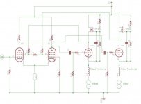
Heres an idea which should solve the issues at the cathodes.
Instead of having the constant voltage MOSFETs at the top, replace them with CCS's. Then in the cathode simply have a transformer with the center tap referenced to a biasing resistor.
So the CCS ensure current balance through the transformer. The DC voltage imbalance at the plates will feedback to the input pentodes which will switch on the opposite side more to compensate, so AC balance should be preserved.
The SLCF element has been lost, but there is less wasted voltage and the transformer is happy and the outputs are working at constant current.
Heres another bonus, since both sides would tend to DC compensate each other - it becomes possible to make the design DC coupled again and if I did - I could eliminate the cathode bias resistor saving wasted voltage.
Comments please.
Shoog
Instead of having the constant voltage MOSFETs at the top, replace them with CCS's. Then in the cathode simply have a transformer with the center tap referenced to a biasing resistor.
So the CCS ensure current balance through the transformer. The DC voltage imbalance at the plates will feedback to the input pentodes which will switch on the opposite side more to compensate, so AC balance should be preserved.
The SLCF element has been lost, but there is less wasted voltage and the transformer is happy and the outputs are working at constant current.
Heres another bonus, since both sides would tend to DC compensate each other - it becomes possible to make the design DC coupled again
and if I did - I could eliminate the cathode bias resistor saving wasted voltage.Comments please.
Shoog
Instead of having the constant voltage MOSFETs at the top, replace them with CCS's. Then in the cathode simply have a transformer with the center tap
That would probably work, but the plate voltage between tubes is going to be larger than it would be with CCS on the cathodes. Because it will regulate current by adjusting plate voltage rather than bias voltage.
- Status
- This old topic is closed. If you want to reopen this topic, contact a moderator using the "Report Post" button.
- Home
- Amplifiers
- Tubes / Valves
- Anyone know of a dual pentode suitable for a LTP.