Does anyone have some simple implementations of a compressor using an optoisolator?
I'm thinking about using the LED as the cathode bias and then the resistor in a feedback loop. Though the datasheets say that the photoresistor needs at least 1 mA current to get a reliable resistance. The photoresistor would be used for Rf in the following (pic from Valve Wizard's site)
So maybe a better implementation is the resistor in the cathode bias and the LED somewhere else?
Or how about the photoresistor used as part of the screen bias of a pentode?
This cool optoisolator must be good for a simple insertion into basic circuits.
I'm thinking about using the LED as the cathode bias and then the resistor in a feedback loop. Though the datasheets say that the photoresistor needs at least 1 mA current to get a reliable resistance. The photoresistor would be used for Rf in the following (pic from Valve Wizard's site)
An externally hosted image should be here but it was not working when we last tested it.
So maybe a better implementation is the resistor in the cathode bias and the LED somewhere else?
Or how about the photoresistor used as part of the screen bias of a pentode?
This cool optoisolator must be good for a simple insertion into basic circuits.
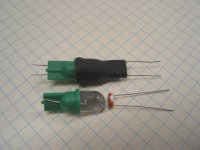
This reminded me of a project I started before The Big Move. It's
an opto compressor using an LED and CdS sensor. The LA-2A
and LA-3A use a phosphor panel but these wear out.
I found an LED close to the bright green color the CdS sensors like
best, and fit them together using adhesive coated heatshrink.
I then plotted CdS cell resistance vs. LED current and voltage (the LED
part has a built-in resistor) and was surprised to find it, while not
strictly linear, to be controllable over a 30 db range or more in an
attenuator circuit.
Anatoliy, that's something I'll have to try. do you use a CdS sensor;
what about time constant?
Cheers,
Michael
Attachments
Wavebourn said:I use LED to sense screen current in output tubes, a photo resistor forms a simple voltage divider with a resistor on the very input of the power amp. It is an anti-clipping compressor I use in all my tube power amps.
Now that is really slick. It took a while for it to sink in but that is an elegant idea.
Michael Koster said:
Anatoliy, that's something I'll have to try. do you use a CdS sensor;
what about time constant?
No, I use Vactrol.
It's too fast to be used as a fair musical compressor: on low freqs outputs get clipped, but the amp itself does not clip.
flysig said:
Now that is really slick. It took a while for it to sink in but that is an elegant idea.
It's Ok, Sometimes it takes few years until people start digging my schematics and constructions that look foolish at first sight.

- Status
- This old topic is closed. If you want to reopen this topic, contact a moderator using the "Report Post" button.