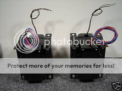
I recently acquired these OPT and would like to create an amplifier worthy of them. Please give me suggestions what you would build with them. I am partial to thoriated filament tubes, perhaps a 6c45p IT coupled to parallel VT-25 tubes? Or VT-25 / 2A3?
Let me know.
Thanks for all your help!
Specifications:
Primary: SE 3000 ohms Primary current: 65ma
Primary, open sec inductance: 16H
Primary loaded sec inductance: 30mh
Primary leakage inductance: 15mh
Secondary: 8 ohms, full silver wire
Power output: 3-5 watts
Bandwidth: -1db 28hz to 30khz
Bandwidth: -3db 13hz to 44khz
I'm getting buried, have I stumped you guys?
Eli has given the sacrilegious suggestion of a DC coupling a ZVP0545A "P" channel MOSFET to a 2A3. This hybrid may sound great and should be sufficient to drive a 2A3 into clipping with a typical 2v input. I am unfamiliar with this, and the sand makes me uneasy, but it has promise of high bandwidth and very high linearity.
What anyone say?
How about a 300B based amplifier, seems that the transformer was designed with this tube in mind from the values you cite.
Something like the EH 300B would be a reasonable choice run fixed bias at 60mA and 350 -400V on the plate.. You could get something >5W in this configuration.
Use something like a triode connected D3A or 5842/417A with CCS loading (you can also use chokes, but this requires selecting driver tubes for proper operating current) and LED cathode bias. Use this to drive a fixed biased 300B. (No colorations from cathode bypass caps.) Use a CCS to power the 300B filaments for low noise. Simple, elegant and a good performer. (I have designed and built several amplifiers along similar lines.)
Eli has given the sacrilegious suggestion of a DC coupling a ZVP0545A "P" channel MOSFET to a 2A3.
If taking a 2A3 into a mild A2 regime is the object, I'd DC couple an IRFBC20 to its grid.
The voltage gain needed to drive a 2A3 is substantial. Look at the data sheet, which shows -45 V. on the grid being "typical". The OP mentioned that he's looking for some "zing", on another forum. I'm wondering if said "zing" can be obtained by incorporating a FET into a 2 stage voltage amplifier/driver. A common source "P" channel ZVP0545A could be DC coupled to a resistively loaded 5687 section. Short loop NFB would be employed around the 2 stages to control net gain and guarantee linearity. The hybrid driver circuitry would be cap. coupled (PTFE film?) to the 2A3.
The 3 KOhm primary impedance of the O/P trafo allows (IMO) easy omission of a bypass cap. on the 2A3's cathode bias resistor. We are talking about some VERY serious linearity.
Eli Duttman said:
<snip>
The 3 KOhm primary impedance of the O/P trafo allows (IMO) easy omission of a bypass cap. on the 2A3's cathode bias resistor. We are talking about some VERY serious linearity.
Actually you'd be surprised, that implies over 3K rp and perhaps 1Wrms output at best, and IMO in my not so limited experience does not sound very good with most speakers due to the high source impedance that results. (The high rp can also interact with the stray primary capacitances in ways that the transformer designer did not anticipate, causing an early HF roll-off inside the passband.) You really do need the cathode bypass capacitor for reasonable power output, damping factor and input sensitivity. (90Vpp drive requirement goes to nearly 200Vpp because of the degeneration at the cathode with no cap, as hard to drive as 300B with about 1/5 the output power.)
That being said I much prefer fixed bias, and a single 300B will give you (a lot) more output power without need for the complexity of power drive, additional stages, or negative feedback even locally applied. Use a 2.5V filament variant of the 300B (JJ 2A3-40 etc) and you can even heat with AC and not have a big issue with hum on the outputs.
Actually you'd be surprised, that implies over 3K rp and perhaps 1Wrms output at best
That being said I much prefer fixed bias
Then consider a Saratov made 2A3 whose operating point is set by combination bias. Use an unbypassed 100 Ω 2A3 cathode resistor in combination with a bias supply. A so called low and hot operating point would be used. The over spec. (for a 2A3) Saratov anode allows the liberty. The net RP and power O/P should match the O/P trafo well.
My objections to the 300B are twofold: its HD spectrum has too much 2nd order to provide the "zing" Buzz wants and many common operating condition sets exceed the power handling capability of the "iron".
Hi Eli,
I will readily concede the second point in particular if an operating point is not carefully chosen, however in the real world I have noted very little difference in harmonic spectra between the 300B and 2A3 in the sort of circuits I employ them in. (FFT analyzer) The old charts are informative but modern tubes don't always adhere very closely to their predictions (in fact the old tubes didn't either, merely representative)
My 300B amplifier certainly has enough "zing," "slam," "extension," "resolution," etc and in terms of those qualities it betters any 2A3 amplifier I have yet encountered.
IMO the biggest things the 2A3 has going for it unless you are talking NOS is lower cost, and less onerous drive requirements. In terms of NOS I really liked the box plate Kenrad 2A3 - had several pairs of these on hand that I used in my 2A3 stereo basic amplifier.
The Sovtek 2A3 single plate is a reasonable choice in some amplifiers, and seems to be quite happy at 55 - 60mA into a 3K primary.. It's also cheap, reliable and rather rugged.
Anyway we haven't heard anything further from Greenvalve, I'm wondering if he could be more specific about what he needs.
Greenvalve: Did the manufacturer specify under what conditions they measured the primary inductance?
greenvalve said:I'm getting buried, have I stumped you guys?
Eli has given the sacrilegious suggestion of a DC coupling a ZVP0545A "P" channel MOSFET to a 2A3. This hybrid may sound great and should be sufficient to drive a 2A3 into clipping with a typical 2v input. I am unfamiliar with this, and the sand makes me uneasy, but it has promise of high bandwidth and very high linearity.
What anyone say?
Could make that a Loftin White version (which makes for excellent PSRR). Here's one shown with a tube based CF. You could easily substitute a MOSFET for the follower stage. Different tube for the first stage is OK too, as long as you have enough gain.
Sheldon
http://www.diyaudio.com/forums/attachment.php?s=&postid=1690207&stamp=1229725484
Hi Kevin, Eli, Sheldon,
These are Electraprint OPT which I have used before. Knowing Jack, I'm sure they are conservatively rated. But to be honest I'm not too excited about another 300B amp since my reference is the 6n1p DRD 300B with copper EPA OPT, regulated b+.
I am stuck on some VT-25 tubes that I just can't get enough of. They sound so realistic and balanced to to bottom that going back to 300B tubes is sort of a let down. (Of course not bad)
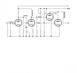
I quickly threw this schematic together just to see something on paper. It gives and idea roughly what I had in mind. Very rough as I have had so little time lately. DC on filaments. Nothings in stone yet.
These are Electraprint OPT which I have used before. Knowing Jack, I'm sure they are conservatively rated. But to be honest I'm not too excited about another 300B amp since my reference is the 6n1p DRD 300B with copper EPA OPT, regulated b+.
I am stuck on some VT-25 tubes that I just can't get enough of. They sound so realistic and balanced to to bottom that going back to 300B tubes is sort of a let down. (Of course not bad)
I quickly threw this schematic together just to see something on paper. It gives and idea roughly what I had in mind. Very rough as I have had so little time lately. DC on filaments. Nothings in stone yet.
Attachments
Even with two tubes in parallel, a 3K load line is pretty steep for that tube (I've built 3 different versions of 801 amps, and the lowest ratio is 10k for a single tube). Maybe OK, but distortion will be fairly high.
Now if you want to really lower the apparent Rp, a single BJT and a couple of other minor parts and you can easily generate 5W with a single VT-25, under very conservative operating conditions, still preserving the tube character. Maybe a transistor with a B of around 5 or so.
http://www.vintage-radio.net/forum/showthread.php?t=13624
Darius doesn't post here now (a bit too rigid sometimes), but he has some cool ideas, and he'll be probably be happy to help if you contact him directly. The LF amp example I posted is a variation on one of his. One of my 801 amps is LW, and it works really well.
Sheldon
Buzz,
You seem to be suffering from # 10, AKA VT-25, on the brain. Use the blasted # 10 to drive a Sovtek 2A3 using the conditions Kevin so kindly provided. The Saratov made monoplate 2A3 is a perfect fit for the "iron" Jack wound.
Obtain the bulk of the requisite voltage gain from a 6SN7 section. DC couple the voltage gain triode to the VT-25's grid. Choke load the # 10. PTFE film cap. couple the driver circuitry to the "final".
You seem to be suffering from # 10, AKA VT-25, on the brain.
Use the blasted # 10 to drive a Sovtek 2A3 using the conditions Kevin so kindly provided. The Saratov made monoplate 2A3 is a perfect fit for the "iron" Jack wound.Obtain the bulk of the requisite voltage gain from a 6SN7 section. DC couple the voltage gain triode to the VT-25's grid. Choke load the # 10. PTFE film cap. couple the driver circuitry to the "final".
Ok, here is what I came up with minus the 6SN7, since I ended up having no good ones. I do have a large stock of the 6s45p however.
An externally hosted image should be here but it was not working when we last tested it.
Nope, too much gain already. Good idea Sheldon, I could also run 2.2v bias and adjust the plate resistor value (which is a guestimate). I have found that battery bias in this configuration has excellent sonics. I just have to make sure the previous stage capacitor output leak resistor is removed or the batteries will drain rapidly.
BTW My wife and I lived for years in San Diego. All winter long we would sneak off to the desert. Have you been to Agua Caliente in Anza Borrego? We moved right after the 2003 fires that ate up Julian to the border.
BTW My wife and I lived for years in San Diego. All winter long we would sneak off to the desert. Have you been to Agua Caliente in Anza Borrego? We moved right after the 2003 fires that ate up Julian to the border.
Buzz,
Cascading the 6С45П (6s45p) and a # 10 yields way too much gain. Heck if you CCS load and buffer it, the Russian "firecracker" provides sufficient gain, by itself. So, there's a dearth of good 6SN7s in your stash. Go buy a few 7N7s or 7AF7s! NICE Emporium, PA, made tubes at comparatively reasonable cost.
I don't know about chokes on both sides of the driver/final coupling capacitor. Fears of resonance and oscillation haunt me. The plate current in a # 10 is modest enough to make CCS loading highly practical. That would take stability issues from chokes surrounding the coupling cap. off the table.
BTW, I'm "chicken" about VR tube snubber cap. value. 47 nF. is less close to the ragged edge and will kill the noise, without as great a risk of oscillation.
Cascading the 6С45П (6s45p) and a # 10 yields way too much gain. Heck if you CCS load and buffer it, the Russian "firecracker" provides sufficient gain, by itself. So, there's a dearth of good 6SN7s in your stash.
Go buy a few 7N7s or 7AF7s! NICE Emporium, PA, made tubes at comparatively reasonable cost.I don't know about chokes on both sides of the driver/final coupling capacitor. Fears of resonance and oscillation haunt me. The plate current in a # 10 is modest enough to make CCS loading highly practical. That would take stability issues from chokes surrounding the coupling cap. off the table.
BTW, I'm "chicken" about VR tube snubber cap. value. 47 nF. is less close to the ragged edge and will kill the noise, without as great a risk of oscillation.
Thanks Eli, I threw a few things in that schematic just to get a sense of pushing the envelope. With the hot front end it wouldn't bother me a bit to use plate resistors and grid leak resistors throughout. I have a few really nice isolation transformers that I could voltage double for a very nice low impedance supply of approx 260v. Would lowering the B+ scape off this excess gain?
greenvalve said:Thanks Eli, I threw a few things in that schematic just to get a sense of pushing the envelope. With the hot front end it wouldn't bother me a bit to use plate resistors and grid leak resistors throughout. I have a few really nice isolation transformers that I could voltage double for a very nice low impedance supply of approx 260v. Would lowering the B+ scape off this excess gain?
The lower voltage will reduce the swing, but not the gain. And Eli's point about alternative N7 tubes is a good one. I've done it myself. Also, the suggestion about the CCS on the type 10 is sensible. I didn't think about it much, but the chokes in series could bounce off each other. Breadboard it up and try a couple of variations before you fab the chassis.
On closer look, the plate voltage seems pretty hot for a regular 2A3 (don't know about the one recommended above).
Sheldon
This is my final shot at using VT-25. If tubes can be matched close enough perhaps current hogging will not become an issue. Will using 250V, instead of 400V on the plates help stability? If you guys think this wont sing, then I'll drop the # 10 type tubes and go with the 6s45p driving the 2A3. In private conversation with Steve he told me a favorite configuration of his was the 3 parallel sv83 tubed monoblocks. Different tube and topology, I know. Maybe the principles apply.
An externally hosted image should be here but it was not working when we last tested it.
- Status
- This old topic is closed. If you want to reopen this topic, contact a moderator using the "Report Post" button.
- Home
- Amplifiers
- Tubes / Valves
- Amplifier suggestions for EPA OPT please