Hi,
I am going to build RH84. I would like to use LED cathode bias for the EL84 - how do I calculate how much leds do I need. I will be using 10mA red leds.
Do I have to use 12AT7 for the input tube? Can I use ECC88 or the circuit demands just 12AT7?
Thank you.
I am going to build RH84. I would like to use LED cathode bias for the EL84 - how do I calculate how much leds do I need. I will be using 10mA red leds.
Do I have to use 12AT7 for the input tube? Can I use ECC88 or the circuit demands just 12AT7?
Thank you.
Attachments
If you are going to build the RH84, build it in strict accordance with the given circuit if you want it to behave like the RH84 should. The configuration of the power supply is up to you, you can even not use a tube rectifier, although it is recommended for the best sound.
If cathode bias of the output tube is done by LEDS, or diodes for that matter, it will not function as it should. Frankly, I do not see why would you want to use LEDS to bias the output tube, maybe some light show?")
The circuit is well balanced and calculated for ECC81 driver and EL84 output tube. Instead of the ECC81 you can use 5695 and E180CC with good results. ECC88 is not at all appropriate for this circuit.
For other attempts try other threads of the forum, as the amp was quite well discussed and documented by those who built it.
If cathode bias of the output tube is done by LEDS, or diodes for that matter, it will not function as it should. Frankly, I do not see why would you want to use LEDS to bias the output tube, maybe some light show?
The circuit is well balanced and calculated for ECC81 driver and EL84 output tube. Instead of the ECC81 you can use 5695 and E180CC with good results. ECC88 is not at all appropriate for this circuit.
For other attempts try other threads of the forum, as the amp was quite well discussed and documented by those who built it.
Hi Alex
I understand that indeed the ECC81 can't be substituted for the ECC88 as the ECC81 spots a higher internal resistance, which is necessary for this circuit to work well...
But about the LED bias for the EL84... As I understand it, LEDs offer a low AC impedance, but provide a DC shift that biases the tube. This is actually the same function as provided by the bypassed 270R resistor in the original RH84, but the leds have the advantage that they don't suffer from blocking distortion due to overload, as thoroughly explained by SY in his "red light district" article. This way it is surely not recommended to use a led to bias the ECC81 (as the unbypassed resistor in the cathode does increase internal resistance), but I think that LEDs can't hurt in the EL84 cathode. Of course it won't be an original RH84 amplifier, but it still will have the local 'plate to plate' feedback and most certainly offer better performance when it comes to overload.
Thank you for your replies.
Ok I will use ECC81/12AT7 for the input.
The cathode LED bias will work, but I dont know how much voltage drop do I need to make with LEDS.
I want to use the same LED biasing technique as in Red Light District.
When I will use 10mA red LEDs, then I will have to use at least 6 strings parallel, as EL84 is biased cca at 47mA. But how many LEDs in each string should I use?
Kacernator
As you already mention the RLD you have probably also seen that SY uses a regulated and adjustable PS for the screens of the EL84's. When using a fixed PS and a output transformer with low RDC one should indeed spend special attention to the current flow, as there is no DC 'feedback': that is, if current increases there is no plate or cathode resistor that counteracts this increase by developing a higher voltage across it and therefore decreasing the voltage (and current) across the tube (the basic of auto-bias).
So, well, I would recommend you to use the same number of leds as used by SY in the RLD and play with the value of the screen resistor to adjust for sufficient, but not to much current. This setting will most certainly not be the best for another tube (as they are all different) so the best thing would be to use an adjustable regulator on the screens...and well, there goes the 'simplicity'
I hope this is more or less right...
Hi Kacernator
Well, overshoot is not nice, I have been told so one should try to prevent it. Here is a nice article discussing it!
http://www.dhtrob.com/overige/pdf/dhtrob_psu.pdf
Well, overshoot is not nice, I have been told
so one should try to prevent it. Here is a nice article discussing it!http://www.dhtrob.com/overige/pdf/dhtrob_psu.pdf
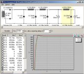
I do not believe that the simulatied voltage curves and overshoot at power-on are fully representative of the actual PS behaviour since the tubes are not drawing any current at that time.
I prefer to supplement with a stepped load simulation after a few seconds to get a better view of the damping (or ringing) under dynamic load conditions.
SveinB.
I prefer to supplement with a stepped load simulation after a few seconds to get a better view of the damping (or ringing) under dynamic load conditions.
SveinB.
As I understand it, LEDs offer a low AC impedance, but provide a DC shift that biases the tube. This is actually the same function as provided by the bypassed 270R resistor in the original RH84, but the leds have the advantage that they don't suffer from blocking distortion due to overload, as thoroughly explained by SY in his "red light district" article. This way it is surely not recommended to use a led to bias the ECC81 (as the unbypassed resistor in the cathode does increase internal resistance), but I think that LEDs can't hurt in the EL84 cathode. Of course it won't be an original RH84 amplifier, but it still will have the local 'plate to plate' feedback and most certainly offer better performance when it comes to overload.
Actually, it is not at all the same whether you use a bypassed 270 resistor, or a string of LEDs (or diodes, for that matter). Try a sim to see for yourself.
The RH amp is not the usual garden variety amplifier, and everything has some reason for being there. To simplify things and make it work "from the first try" and every time in the same way, you have to renounce some unnecessary complications.
The overload is not an issue here, since the final performance of the amp will depend on the interaction between driver and output tube -- when the two waves meet, there is no point of going further... what you did get was before that point, and you do get it without other complications.
Finally, a good resistor costs less than a string of LEDs, and dissipates heat much better?!?!?!
Last but not least, I like them built as they were once: no sand of any kind, and possibly point to point
After all I think I will sacrifice little of performance for the simplicity, so will go with resistor cathode bias.
YES, MAN! You will not sacrifice any performance (the opposite in this case) but simplicity is paramount!
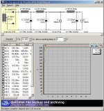
Lastly, what do you think of this PSU?...attached imaged.
You must be young!
Anyway, the overshoot in this case does not matter. What matters is that you should use a resistor instead of the constant current: tubes will start conducting gradually... and will not draw the same current regardless of the B+.The power supply is basically an overkill. If you can use more than one choke, desto besser do an LCLC combination... and of course WITH tube rectifier for the best sound
The problem with sims is that people tend to take them literally and apply to any given situation. Actually, a sim works fine for one and only one situation and a lot of times you have to adjust things with additional elements in order to have the best possible approximation of the circuit's behaviour. For instance, I use to represent the output transformer as a resistor (Ra) in parallel with a choke (L of the primary) and between that and the power supply I insert a resistor in series representing the RDC of the primary. Basically, what is missing is the load reflected in the primary, but there is such a thing as negligibility. On the other hand, a lot of people use transformer models, which might or might not be the best approach to a given problem.
The amp needs approx. 100mA DC (high voltage) in total for both channels.
The output tubes draw approx. 40 mA thru the primary of the OT. The OT should have a primary able to work with 50mA DC without saturation.
The amp needs approx. 2A of 6.3V AC for the heaters, and additional secondary for the rectifier if you are using a tube rectifier.
The output tubes draw approx. 40 mA thru the primary of the OT. The OT should have a primary able to work with 50mA DC without saturation.
The amp needs approx. 2A of 6.3V AC for the heaters, and additional secondary for the rectifier if you are using a tube rectifier.
- Status
- This old topic is closed. If you want to reopen this topic, contact a moderator using the "Report Post" button.
- Home
- Amplifiers
- Tubes / Valves
- RH84 questions