D. Self 6th ed.
butterfly wing plots start on page 238, 239 ....
Attachments
MTA (Multiplied Transconductance Amplifier)
Any of the pundits here have any views on Frank Blöhbaum's MTA (Multiplied Tranconductance Amplifier) topology?
It is not in the public domain, but there is a taster here ...
Linear Audio Vol 6 Preview
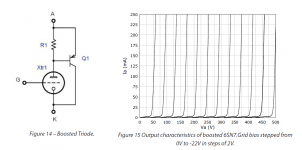
In the article a boosted triode drives the pentode of a common cathode tube (e.g. ECL80), and the measured results look very good.
Jan Diden posts here - maybe he could preview the work without infringing anyone's intellectual rights?
Any of the pundits here have any views on Frank Blöhbaum's MTA (Multiplied Tranconductance Amplifier) topology?
It is not in the public domain, but there is a taster here ...
Linear Audio Vol 6 Preview
In the article a boosted triode drives the pentode of a common cathode tube (e.g. ECL80), and the measured results look very good.
Jan Diden posts here - maybe he could preview the work without infringing anyone's intellectual rights?
Attachments
Last edited:
What is the reason this kind of plots have not been done (or at least officially reported) on tube amps?
I can only guess that this was done way back in some research journal and they concluded that all class AB tube amps would have the same crossover curves.
So no need arose to develop some test equipment back then. Of course, with more fancy local Fdbk schemes this is useful.
I think the 1st place I encountered gm wing plots was an early SS amplifier design handbook by Dennis Feucht, but these probably precede that. With all the SS device types and complementary devices would have come a need for gm wing plots for class AB crossover.
With precision A/D chips and microprocessors, the Audio Precision Analyzer type devices became possible. The gm wing plots likely were just a software add-on to the FFT capability. Digital subtraction of adjacent samples, with some averaging for noise suppression. Pretty easy to add on.
I have not seen any mention of the simple analog differentiator scheme before, but it would be an obvious solution back in analog only times for doing such tests.
--------------------------------------------------------
Frank Blöhbaum's MTA (Multiplied Tranconductance Amplifier) topology?
These hybrid Darlington and Complementary Feedback Pair (CFP) designs have been around for a long time. Some versions have a CCS added to keep tube current constant too. Both got patented well -after- public disclosures and are pretty obvious to most SS designers. Just a device substitution into a standard textbook circuit.
They should work fine if device characteristics like constant Beta or Mosfet capacitance are well controlled. And then there are still crossover dist. and SS temperature stability for idle current issues for P-P stages that have to be well controlled. This puts one right back into the usual SS amplifier design issues, but with tube drift added too. But if well controlled, they could replace OTs for high current output. A lot of SS support circuitry needed to control these issues well enough for a product use.
More sensible for SE designs.
But then there is no attractive power tube used for visuals since the SS device does the heavy lifting, big heat-sinks instead. I would put them into the interesting idea, but not attractive to high end buyers category. More of a DIY thing to avoid an expensive OT.
Last edited:
Any of the pundits here have any views on Frank Blöhbaum's MTA (Multiplied Tranconductance Amplifier) topology?
It is not in the public domain, but there is a taster here ...
Linear Audio Vol 6 Preview
In the article a boosted triode drives the pentode of a common cathode tube (e.g. ECL80), and the measured results look very good.
Jan Diden posts here - maybe he could preview the work without infringing anyone's intellectual rights?
Same idea as the "Triodelington" by another German Nerd
Sorry to quote a very old post, but I would like to know if the user is still frequenting this forum to know if he has performed further tests. I experienced the same results with a similar design (without gnfb) obtaining a very pleasant balance (UL + AA + AS).Anode-to-Anode (AA) gives a great sense of clarity but also tended to sound lightish in balance. The the Anode-to-Source (AS) loop pair was introduced and this had the exact opposite effect. If AS was balanced against AA, then the balance could be "dialled" in. If AS was allowed to dominate, then the sound would sound to rich and too dark and taking out AA alltogether and it would sound positively weird.
Crazy Drive?
I missed the "Crazy Drive" discussion. From the curves, it looks related to this scaled g1/g2 drive thread from a decade ago?
G1=G2/mu Scaled Drive Strawman Design
Been a while since I saw this thread.
The WE HE doesn't seem to have caught on at all obviously.
...
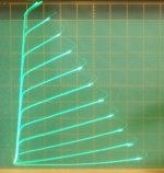
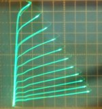
On the original topic of new developments in tube amplifiers, I would say the real developments are Crazy Drive, which gives TV Sweep type tubes constant gm, a major breakthrough. Even class aB can operate as first order linear with that.
Then more recently, "new" series Schade (or CED, UnSET at Tubelab) have given us the ability to make high quality constant mu triodes (also the ability to adjust the amount of second harmonic if wanted). These triodes can be far better than the internal triode wired configuration previously available. The "shunt Schade" local N Fdbk schemes available before have an inherent flaw in the resistor derived N Fdbk, due to the low single stage gain allowing grid drive V to mix with N Feedback V in the Fdbk current derived in that resistor.
pics:
a) Crazy drive
b) "new" series Schade (CED, UnSET)
c) conventional grid 1 drive
d) conventional internal triode (note the curve "rollover" effect causing 2nd harmonic)
I missed the "Crazy Drive" discussion. From the curves, it looks related to this scaled g1/g2 drive thread from a decade ago?
G1=G2/mu Scaled Drive Strawman Design
Hi Michael, good to hear from you again here.
The Crazy Drive scheme does drive both grid 2 and grid 1, so is somewhat similar to the old dual drive scheme. But Crazy Drive only provides a driver for grid 2, the grid 1 drive is derived from that with just a series resistor from grid 2 to grid 1. (and another resistor from grid 1 to cathode)
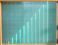
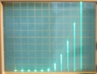
Grid 1 operates in positive territory, and has a "Crazy" drive characteristic due to grid 1 current being important. Grid 1 voltage variation progressively drops out as grid 1 current holds down its voltage. So grid 2 progressively takes over. Grid 1 current is approx. square root of grid 1 voltage, so it reduces grid 1 contribution by a square root factor, becoming linear. With adjustment of the divider resistors to grid 1, the whole thing can achieve constant gm over a wide range. Curves below. 50mA/div Vert. 50V/div Horiz. (easily working to 1/2 Amp and beyond for Sweeps) Works with most any TV Sweep tube, essentially just wants a low grid 2 drive voltage range. The grid 1 contribution typically drops the grid 2 drive Voltage requirement by another 25 to 30% besides. + Grid 1 drive dissipation stays reasonably low, mW. Notice the lack of screen current kinks in the Crazy Drive curves as well. (compare to grid 1 drive curves below)
a) Crazy Drive plate curves - 26LX6
b) Crazy Drive Vg to Ip curve
c) Conventional Vg to Ip curve
d) Conventional grid 1 drive - 26LX6
The Crazy Drive scheme does drive both grid 2 and grid 1, so is somewhat similar to the old dual drive scheme. But Crazy Drive only provides a driver for grid 2, the grid 1 drive is derived from that with just a series resistor from grid 2 to grid 1. (and another resistor from grid 1 to cathode)
Grid 1 operates in positive territory, and has a "Crazy" drive characteristic due to grid 1 current being important. Grid 1 voltage variation progressively drops out as grid 1 current holds down its voltage. So grid 2 progressively takes over. Grid 1 current is approx. square root of grid 1 voltage, so it reduces grid 1 contribution by a square root factor, becoming linear. With adjustment of the divider resistors to grid 1, the whole thing can achieve constant gm over a wide range. Curves below. 50mA/div Vert. 50V/div Horiz. (easily working to 1/2 Amp and beyond for Sweeps) Works with most any TV Sweep tube, essentially just wants a low grid 2 drive voltage range. The grid 1 contribution typically drops the grid 2 drive Voltage requirement by another 25 to 30% besides. + Grid 1 drive dissipation stays reasonably low, mW. Notice the lack of screen current kinks in the Crazy Drive curves as well. (compare to grid 1 drive curves below)
a) Crazy Drive plate curves - 26LX6
b) Crazy Drive Vg to Ip curve
c) Conventional Vg to Ip curve
d) Conventional grid 1 drive - 26LX6
Attachments
Last edited:
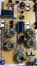
I would certainly say ZOTL is still modern. Just not adopted much. Would be nice if someone would make a PC board driver for everyone to use. A PCM type controller chip to get the complementary square wave drive signals (with a built in crossover dead time) and a high side driver chip to drive the top side Mosfets. Could provide mounting positions for the 4 power Mosfets on a heatsink at the edge. Just have to wind some Ferrite xfmrs then.
There are some other versions around too. Can use a two phase capacitive voltage multiplier stack instead of the ferrite xfmrs for example. Anything that will voltage multiply up to enough HV to operate the tubes.
There are some other versions around too. Can use a two phase capacitive voltage multiplier stack instead of the ferrite xfmrs for example. Anything that will voltage multiply up to enough HV to operate the tubes.
Last edited:
And don't forget the "new" series Schade local N Fdbk scheme (CED and UnSet at Tubelab)
With this you can make a high quality triode rivaling a 211 from most any TV Sweep tube or any tube for that matter. Can make 2nd Harmonic programmable as well. Can tune it to be a 300B if you want. High current Sweeps will make for practical OTs too (unlike most transmitting tubes).
This uses the old "shunt Schade" local N Fdbk scheme, R from plate back to grid 1, (then another R from grid 1 to ground) but the input drive is shifted to a P Mosfet follower driving the tube's cathode instead (not a cascode, this is using a follower). This avoids a distortion mechanism that was hidden in conventional "shunt Schade" where the grid 1 drive messed up the current in the Fdbk resistor due to typical single tube low loop gain.
The driver power gets added to the tube output power as a bonus.
Last edited:
- Status
- This old topic is closed. If you want to reopen this topic, contact a moderator using the "Report Post" button.
- Home
- Amplifiers
- Tubes / Valves
- Modern tube amplifier designs?