Hi all,
I am in the process of testing my version of this 845 amp -
http://www.audiodesignguide.com/New845/New845v2.html
With respect to Bias, Ciuffoli (the designer) recommends a bias voltage of -120V.
My plate voltage is around 940v.
OK, so I set the amp up with this bias voltage on both channels. No problems and all works well with stable readings. However, I have also placed a 10 R resistor between cathode and ground on both tubes. With the bias equal and at -120v in both tubes, the voltage drop across the cathode resistor of 'tube 1' is 0.81v (81 mA current). The voltage drop across the cathode resistor of 'tube 2' is 0.74v (74mA current).
I have a couple of questions if anyone has some good ideas/opinions -
1. Why the discrepancy in plate current when the bias voltage is equal and stable in both tubes?
2. Should I be biasing to bias voltage (-120) or plate current as measured indirectly across the 10 R resistor?
3. If above what current, 70 mA, 80 mA or something else?
Finally, looking at the 845 data sheet, a bias voltage of -120 gives a plate current of around 120 which is right on the upper tolerance of the tube.
In short, I am not sure what to believe. The data sheet suggests that a voltage of -120 is to small but my indirect measure of plate current suggests that -120 is about right.
Any ideas?
Rob
A real tube (as opposed to the Platonic ideal of the datasheet) is made of glass and metal, assembled and evacuated. Wound wires, rods, bent sheet metal, spot welds. There are all sorts of mechanical tolerances, and the materials themselves vary. Lots of different manufacturers make nominally the same type of tube using different machinery, different operators, different materials suppliers. The question is not, "Why is there any variation in current with a fixed bias voltage?" but rather, "Why isn't there MORE variation?"
If it were desired to have a fixed bias voltage and let the current go where it may, then there wouldn't be any bias adjust controls. As Frank said, adjust the bias for the proper idle current.
If you ever work with FETs, you'll be shocked. You'll see fundamental parameters varying 5 to 1 between units.
Thanks Sy and Frank,
I think that this answers my question (aside from a new one below).
OK, so the best way to set bias is by cathode current.
I have an indirect measure of this by measuring voltage across a 10 R resistor and this comes in at between 0.74 v (74 mA) and 0.81 v (81 mA) with a grid voltage of -120. So, if I set them up to read 0.8v in both tubes idling (I presume this is with volume right down) then my current should be 80 mA - provided my measuring is OK.
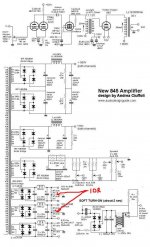
This leads me to my final question. Have I set up my 10 R resistors appropriately? I have included the schematic with my modification.
Thanks again.
Rob
I think that this answers my question (aside from a new one below).
OK, so the best way to set bias is by cathode current.
I have an indirect measure of this by measuring voltage across a 10 R resistor and this comes in at between 0.74 v (74 mA) and 0.81 v (81 mA) with a grid voltage of -120. So, if I set them up to read 0.8v in both tubes idling (I presume this is with volume right down) then my current should be 80 mA - provided my measuring is OK.
This leads me to my final question. Have I set up my 10 R resistors appropriately? I have included the schematic with my modification.
Thanks again.
Rob
Attachments
hey-Hey!!!,
I think that McIntosh is the only one who has offered fixed, fixed bias...in your 845 case twist the knob to deliver grid voltage to equalize current between the two tubes. Sy is exactly right, there is lots of variation, even with so-called 'matched pair' sets of tubes. I think your pair is pretty close, adjust for equal plate current and dismiss such worries from your thoughts...")
cheers,
Douglas
I think that McIntosh is the only one who has offered fixed, fixed bias...in your 845 case twist the knob to deliver grid voltage to equalize current between the two tubes. Sy is exactly right, there is lots of variation, even with so-called 'matched pair' sets of tubes. I think your pair is pretty close, adjust for equal plate current and dismiss such worries from your thoughts...
cheers,
Douglas
- Status
- This old topic is closed. If you want to reopen this topic, contact a moderator using the "Report Post" button.