"Wrong! Don´t forget there is no external load on the Aikido-triode as it is feeding a CF."
Whoaa, wait a minute.
Assuming the upper triode Rp matches the Rp of the of the lower triode in the Aikido, it just cuts Mu in half by paralleled Rp's. (well, some corrections needed for the Rk's lowering Mu a bit) I worked out a theoretical 3/2 power math model for the Aikido once and it comes out quite clean.
For the shunt feedback thru a diode case: (configuration: output pentode plate connects to the diode's plate besides it's output load. The diode's cathode connects to the triode driver's plate. Grid drive signal for the output pentode is taken from the triode driver plate, thru a cap etc. as usual):
With a diode load of say 10X Rp of the triode below (for the same current), and an (O.L.) gain of say 20X in the output stage, the diode load will then look like 1/2 Rp of the triode effectively (due to the 20X anti phase of the output signal, or 20X anti-bootstrapping). (there will be increased current thru the triode and diode due to this extra loading factor, so this lowers their Rp's even further yet. but they will remain in a constant ratio still, since the same current goes thru both triode and diode)
Higher feedback would use a lower Rp diode, becoming even less than 1/2 triode Rp effectively. The triode in each case just gets a lower Mu effectively from the non-linear loading, but still retains its linearity. (assuming the non-linearities of the diode and triode track, which should be reasonable for plate/cathode Rp's)
So the driver loading could be brought all the way down to 2K effective if needed, but would still give a linear gain, just less. The key here is the load/feedback diode is matching the non-linearity of the driver's plate, maintaining a fixed attenuation ratio. Whereas the usual fdbk resistor is just "too" linear.
Don
Don,
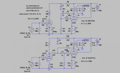
I looked at the Aikido as a simple mu-follower with a very small bootstrap resistor of 250 ohms, albeit with the output taken below instead above the bootstrap-resistor. I did a quick calc and came to the conclusion that the lower triode should look into something like 15-20k.
When trying to verify I was then a little surprised when simming and finding out that the Aikido/mu-f./srpp/whatever 12AT7 simmed exatly like a 12AT7 with a anode resistor of 27k and an unbypassed Rk of 250ohm. Both gain, freq. and distortion alike. So the bootstrap-effect seems to be higher. Can do the same sims with a few other triodes to verify.
So I still believe there is a big difference between 27k and 1,75k ohms load and that "circuit 1" is a very bad way of adding feedback. Will still only work OK with pentodes as it was initially intended for them.....
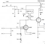
Since the topic title refers to O.H.Schade, i played with LTspice to make a SE version of the circuit in his paper "BEAM POWER TUBES" from 1938. (the paper can be downloaded here: http://www.one-electron.com/Misc_Docs.html)
The interstage transformer coupling removes the problems we are discussing of (over)loading the driver tube and/or reduced gain.
Yes I know we may select a better driver tube than the 12AT7, and I also suspect that IT coupling present some new challenges, as well as the added cost, but it sure sims nice")
SveinB
The interstage transformer coupling removes the problems we are discussing of (over)loading the driver tube and/or reduced gain.
Yes I know we may select a better driver tube than the 12AT7, and I also suspect that IT coupling present some new challenges, as well as the added cost, but it sure sims nice
SveinB
Attachments
Heja Svein,
Seriously, you can not mean it sims nice like it is . First of all you have to bypass the 12AT7 cathode resistor. The IT also has to be something like 200H to work OK. As it is -3dB is at 300Hz.
But IRL it would maybe not be worth the extra money . Will sim it against my other circuits.
EDIT: Simmed the two side by side and the IT is a tad better with respect to THD. Sensitivity is doubled. But due to the IT lowend response is worse.
Seriously, you can not mean it sims nice like it is
. First of all you have to bypass the 12AT7 cathode resistor. The IT also has to be something like 200H to work OK. As it is -3dB is at 300Hz.But IRL it would maybe not be worth the extra money
. Will sim it against my other circuits. EDIT: Simmed the two side by side and the IT is a tad better with respect to THD. Sensitivity is doubled. But due to the IT lowend response is worse.
Attachments
O.H.Shades paper on beampower tubes is with respect to some issues hard to follow. On Pete Millets site there is an article http://www.pmillet.com/Books/bbc_feedback.pdf
where the construction of ia/ua for a Shaded tube is easier to understand.
I am working on a project with 13E1, and as an alternative to a std triode connection, I am about to have a closer look at plate to grid feedback.
I have spent some hours making tetrode ia/ua curves for 13E1 as the ones in the datasheet does not cover area of interest.(measurements not finnished)
Sorry for interrupting the thread, but as the heading refers to Shade....
What I am searching for is an article going through some of the calculations to set up a driver and a Shaded beampower tube output stage.
Also looking for a more detailed explanation of the use of interstage trafo as shown in Svein's drawing.
Attachments
And cathode feedback can produce a Schading effect.
Stand the tube on one of your secondary windings.
Some PushPull will have the 4ohm Grounded. Cause
the common and 16 are actually tied to the cathodes.
Same thing, only different....
Any variance at Cathode looks just like a variance in
the grid, only inverted....
Stand the tube on one of your secondary windings.
Some PushPull will have the 4ohm Grounded. Cause
the common and 16 are actually tied to the cathodes.
Same thing, only different....
Any variance at Cathode looks just like a variance in
the grid, only inverted....
Hej Vega65!
The detailed explanation is all in the Schade-paper Svein linked to.
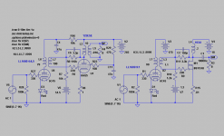
Sveins circuit has a few tiny faults and will not work properly IRL.
If you instead check the 2nd circuit in my post after his I have corrected them to a working one with active components relevant to this thread.
Can mail you the *.asc file together with tube models to play around with. This way you will learn by simming .
The detailed explanation is all in the Schade-paper Svein linked to.
Sveins circuit has a few tiny faults and will not work properly IRL.
If you instead check the 2nd circuit in my post after his I have corrected them to a working one with active components relevant to this thread.
Can mail you the *.asc file together with tube models to play around with. This way you will learn by simming
.pmillett said:
hey-Hey!!!,
Nice...TX-coupled E-Linear...
I will be sure to find that aX issue when you've got your article in it.cheers,
Douglas
Heja Svein,
You where on the right track when you exactly followed Schades original circuit. This is the way to go!
With quite a few tricks and tweaks this will make a nice amp, and why not make it MOSFET?
The 6AQ5 will have less than 1% THD with triode characteristics at 4W. The MOSFET 10W below 1% with 18V B+!
Attachments
 .
. - Status
- This old topic is closed. If you want to reopen this topic, contact a moderator using the "Report Post" button.
- Home
- Amplifiers
- Tubes / Valves
- Schade84